In the past, when designing a digital audio system, engineers needed to have relevant knowledge and experience, and also spent a lot of time and effort on software development. ROHM's USB HOST audio decoder greatly simplifies the design process, and software decoding is implemented internally by the chip, making it easy for designers to build digital audio systems.
This article refers to the address: http://
The design of traditional CD playback systems and MP3 players usually requires memory controllers, decoders, DACs, system controllers, etc. These modules are scattered in various ICs, and the Hardware and software design are complicated. The USB HOST audio decoder integrates these functions into a single chip, requiring only a small amount of crystal and RC components externally, which greatly reduces the cost and improves reliability.
Chip function
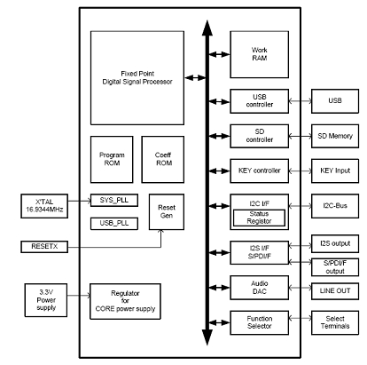
All decoding work in ROHM's USB HOST audio decoder is done automatically by hardware, which is different from other embedded CPU designs, which reduces the complexity of software programming. Internally integrated USB and SD card controllers provide direct access to files in memory. The chip sorts the music files in the memory in Unicode encoding and plays them in order. Built-in FAT file system, can automatically distinguish between music files and non-music files. The chip can also automatically skip the damaged file to prevent noise. The chip has a built-in Keyboard controller that can be connected to a 4 X 3 button matrix. The audio output supports both analog and digital outputs. The speaker amplifier can be directly connected to the analog output, and seven sound equalizers are built in, which can be selected by the I 2 C bus at the output. The digital output supports highly versatile I2S BUS and SPDIF, which can be easily connected to the next level of digital signal processing circuitry. The chip has an I 2 C bus interface built in to communicate with the microcontroller. The functional block diagram of the USB HOST audio decoder is shown in Figure 1.

Figure 1: Functional block diagram of the USB HOST audio decoder.
The music file operations executable by the chip include: play, pause, stop, fast forward/rewind, jump to next/previous song, repeat play, random play, volume adjustment, file browsing, read ID3 information, and the like.
The chip has three operating modes that can be selected via function pins:
Mode 1 is also called "independent mode". The chip does not need an external microcontroller when working, and can directly play the music file in the memory as a host, and select the play mode by reading the external key operation through the built-in keyboard controller. The chip also has built-in 7 LED driver interfaces, which can clearly understand its working mode through the rich performance of LED. In this mode, the chip also supports the auto play function, which automatically reads and plays the music files in the memory after power-on, without external intervention.
Mode 2 and Mode 3 are called "slave mode". The chip requires an external microcontroller to transmit instructions through the I 2 C bus, and the designer needs to write the appropriate control software. The implementation of these two modes is more complex than mode 1, but can build higher performance systems. Among them, the mode 2 workflow is similar to the mode 1 key input, and it is necessary to perform operations such as "PLAY" and "PAUSE" by receiving an instruction from the microcontroller. In mode 3, the chip transmits the location of the music file in the memory to the microcontroller via the I 2 C bus, and then the controller selects the play by specifying the location of the file. During playback, the chip will read the playback time every 100ms, and the information such as the playback time and track name of the track can be displayed through the LCD. In both modes, the chip also has the RESUME function, which can be resumed from where it was last stopped during the next playback.
Design implementation
This article will introduce a design example of a digital audio system consisting of ROHM's USB HOST audio decoder BU9437AKV and NEC's 16-bit microcontroller uPD1166. The BU9437 supports MP3 and WMA file decoding with all the features of the USB HOST audio decoder chip described above.
1. hardware design
The hardware circuit is mainly designed with reference to the slave mode of BU9437. The control information sent by the MCU is received through the I 2 C bus to realize the functions of mode 2 and mode 3.
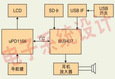
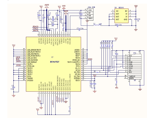
The BU9437 is equipped with an SD card and a USB interface. In order to protect the USB device from being damaged during hot plugging, we also designed a USB protection switch that uses ROHM's USB High Side Switch chip. The audio output uses an analog stereo output with an external headphone amplifier that can be heard through headphones or powered speakers. The MCU is connected to a five-way switch for easy menu selection. The LCD is a 16 X 2 character dot matrix liquid crystal that can display simple screens such as function menus and file information. The chip communicates with the MCU via the I 2 C bus. The hardware system block diagram is shown in Figure 2, and the BU9437 application circuit is shown in Figure 3.

Figure 2: USB HOST digital audio system block diagram

Figure 3: U9437 application circuit diagram
2. software design
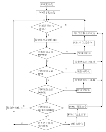
The software is designed to use the MCU's keyboard interrupt to judge and identify the key value. The main program loops through the key value and BU9437 status, sends different commands to BU9437 according to the key value, and displays the working status of BU9437 on the LCD. The main program flow chart is shown in Figure 5.

Figure 5: Software Flow Chart.
The operation of the navigation key is handled by using an interrupt. When any button is pressed, a key interrupt is generated. In addition to the anti-shake, the priority of the key is determined in the interrupt program, and the key value of the key is directly obtained in the interrupt program.
The LCD module has an 8-bit data line and a dedicated subroutine is written to send the display data.
The control of USB HOST chip is realized by I 2 C bus. The software also designs the corresponding I 2 C communication program to make it meet the communication protocol of I 2 C bus. The communication timing is shown in Figure 4.

Figure 4: I 2 C bus communication timing.
3. Design considerations
1. The USB HOST chip needs to be connected with a 16.96344MHz crystal oscillator. If a passive crystal oscillator is used, pay attention to the starting condition of the crystal oscillator. Select a suitable oscillating circuit to ensure that the crystal oscillator can work normally after the chip is powered on.
2. When selecting analog audio as the output, it is best to separate the analog ground from the digital ground in the PCB design, and increase the capacity of the filter capacitor or tantalum capacitor at the time of power input to suppress noise.
3. In order to increase the reliability of the software, when reading the value of the register, the first byte read is the busy state of the system, and the software must process this byte each time it is read.
Summary of this article
ROHM's USB HOST audio decoding chip is not only suitable for vehicle-level applications, but also for music-independent devices such as toilets and health care equipment. It can simply play therapeutic music and natural environment sounds. In addition, it can also be used for the sound of entertainment equipment, the playback of sound effects, and the sound of sounds such as in-vehicle broadcasting of public transportation. In this case, the voice data is stored in the USB memory or the SD memory card, so when the voice data needs to be updated, it is fast and convenient.
China Diy Game low price
Guangzhou Ruihong Electronic Technology CO.,Ltd , https://www.callegame.com