Author: Qi Pengfei    WeChat: qipengfei-yp
I watched the video of 2017 Chevrolet Bolt EV Battery Disassembly some time ago . Now I will disassemble the data and summarize it. I hope you can analyze more information.
First, the overall system description
Battery system group way 3P96S, a total of 288 cell, consists of eight modules and two 3P8S 3P10S module, wherein the power module is 3P10S 5.94kWh, 3P8S power module is 4.74kWh, total power system 57kWh .
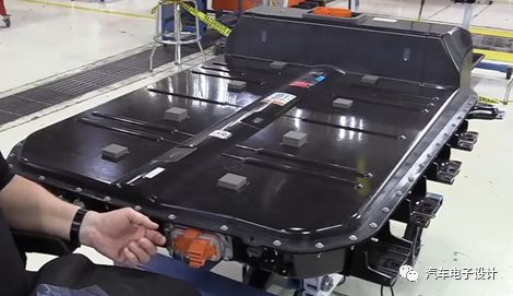 Â Â Â Â Â Â Â
      Â
Battery system appearance

Battery pack label
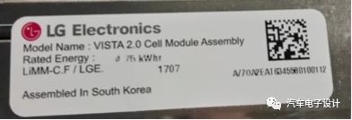
3P8S module label
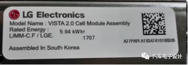
3P10S module label
The actual assembly, a 3P10S 3P8S module and a module composed of a large module, two modules form a large 3P10S module arranged five major modules in the battery pack. If only the module structure is considered, it can be designed as 3P20S and 3P18S . The large module is divided into two small modules, and the plastic frame in the middle of the module is connected through the sheet metal member and the lower box beam, and the module end plate and the box body are connected to realize the fixing of the module. In addition, the module is divided into two to facilitate the high-voltage copper row connection in the box, and the MSD is arranged in the middle of the high-voltage circuit.
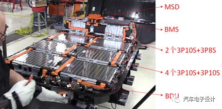
Arranged inside the battery pack
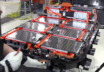
High voltage copper row connection
Second, the box structure
The lower box body adopts the sheet metal stamping structure, and four live beam are arranged in the box body . The beam is set to be a live load mainly for making the liquid cooling plate of the lower four modules into one whole, reducing the liquid cooling system piping and joints, and reducing Liquid leakage risk and cost.
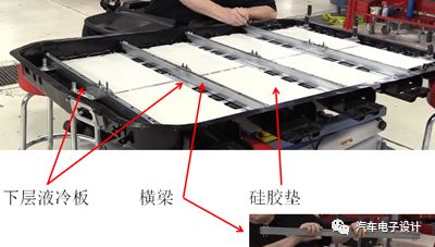
Lower case structure -1 (including insulation pad, liquid cooling plate, silicone pad, beam)
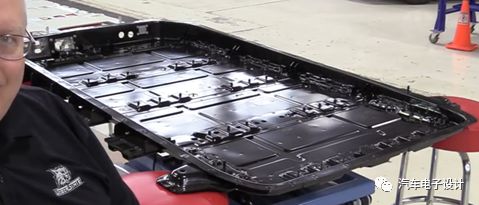
Lower box structure -2
The figure below shows that the wall thickness of the box is very thin, and the weight reduction effect of the lower box is obvious.
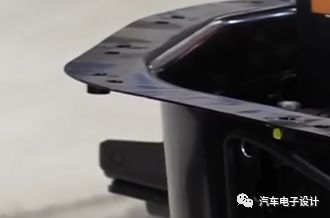
Lower box body
The upper cover bar code display shows that the upper cover is made of composite material > UP-GF45< . When the cover is removed, the fixing screws of the cover and the box are directly pressed on the upper cover, and the metal bead is not used to isolate the screw and the cover, indicating that the structure and material of the upper cover can withstand the screw pressure.
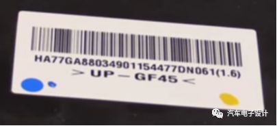
Upper lid barcode
Third, support fixed structure
The two end plates of the lower module are fixed on the box body; the plastic frame in the middle of the module is fixed on the lower box beam by the sheet metal member; and the sheet metal member is fixed on the lower box beam by the sheet metal pressing module.
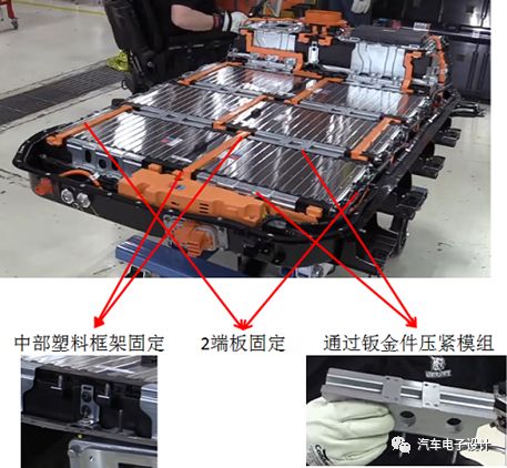
Lower module fixed structure
The position of the double-layer module, the outer layer of the lower module is provided with a sheet metal bracket, and the lower layer module is also provided with a supporting structure on the sheet metal, and the upper layer supporting the sheet metal (for supporting the liquid cooling system) is fixed, and then the upper layer is separated. The heat pad, liquid cooling plate, silicone pad and module are sequentially fixed. Finally, the plastic frame in the middle of the upper module is fixed by sheet metal, and the upper module is pressed with sheet metal.
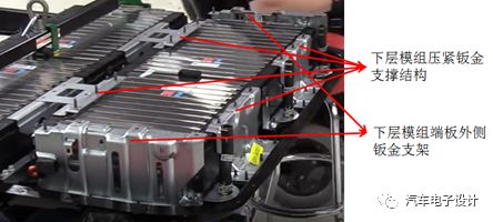
Upper module support structure -1
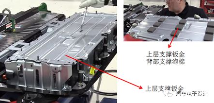
Upper module support structure -2
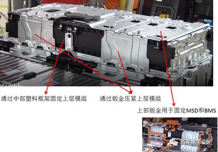
Upper module support structure -3
As can be seen from the figure below, the upper module is positioned behind the lower module, so that the arrangement can facilitate the arrangement of the upper module support structure, and the lower right position of the upper module can be used for the arrangement of the upper and lower liquid-cooled plate connecting pipes. Space is not wasted.
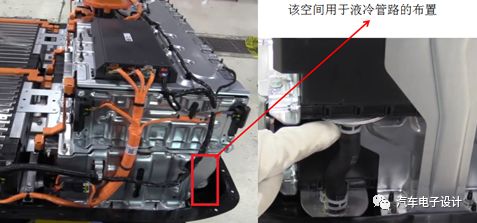
Upper and lower module layout
Fourth, liquid cooling system
The inlet and outlet of the liquid cooling system are divided into male and female ends, the left side is the water inlet, and the right side is the water outlet.
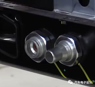
Inlet and outlet structure
The lower 4 layers share one liquid-cooled plate, and the upper module uses one liquid-cooled plate. The water inlet joint is connected with a three-way nylon tube, and the other two interfaces of the three-way tube are connected through the quick-connect joint and the lower liquid-cooled plate inlet. The outlet joint is connected to a nylon tube, and the other end of the nylon tube is connected to the lower liquid-cooled plate outlet. The upper and lower liquid cooling plates are connected by three rubber hoses and clamps.
The complete list of liquid cooling system parts is as follows:
1 ) Inlet connector (including three-way nylon tube + 2 push-in connectors)
2 ) Water outlet connector (including nylon tube + 1 push-in connector)
3 ) 3 rubber hoses (including 6 clamps)
4 ) 1 lower liquid cold plate, 1 upper liquid cold plate
5) 8 3P10S thermally conductive pad of silica gel, a thermally conductive silicone pad 2 3P8S
6 ) 5 insulation pads
As can be seen from the above list, there are few joints in the liquid cooling system, which reduces the risk of liquid leakage and cost; the other two nylon tubes are hard tubes without bellows. This shows that the manufacturing precision and assembly precision of the parts such as the cabinet, the liquid cooling plate and the module are better controlled.
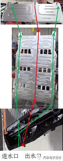
Liquid cooling system coolant flow direction
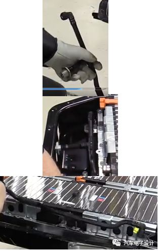
Inlet tee
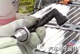
Water outlet nylon tube
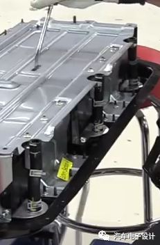
Rubber tube and clamp connected to the upper and lower liquid plate
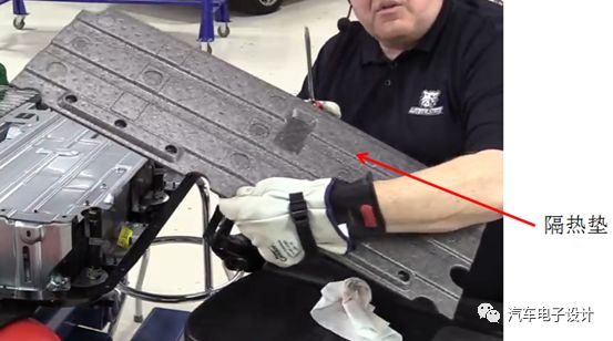
Insulation pads
Regarding the liquid cooling system, there are several questions I would like to share with you:
1 ) The size of the lower liquid-cooled plate is very large. Which liquid-cooled plate manufacturers in China can process liquid-cooled plates of similar size?
2 ) The flow path of the liquid-cooled plate is relatively wide. How to solve the problem of deformation and bulging when the liquid-cooled plate is pressed?
3 ) What is the insulation mat material?
4 ) The liquid cooling system does not use elastic support. How to ensure that the liquid cooling plate is not damaged in the vibration environment?
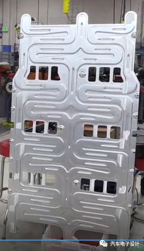
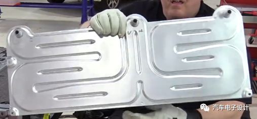
Upper and lower liquid cold plate
Fifth, the module structure
The BOLT module uses a plastic frame and a long screw group structure.
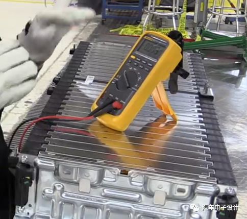
Module shape
The module BUSBAR adopts ultrasonic welding technology, the BUSBAR copper row is fixed by hot riveting, the BUSBAR copper excludes the output row nickel plating, and the others are bare copper bars. Voltage acquisition is achieved by copper strip extension structures and PCB board soldering. These several methods are also commonly used by LG .
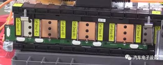
This time, I will summarize so much information, and I will have more information to communicate with you.
IO Cable Plug
Feyvan Electronics provides many different solutions of IO cable plug for CNC (computer numerical control) machine tool fittings of different systems.
Related connectors brand: AMP, HONDA, JAE, INC, HIR, DDK, 3M, HYPERTAC, Fujistu, etc.
We have designated agents for all the connectors brands.
Meanwhile, we also could produce copy connectors of the brands above which can obviously lower your costs.
All the connectors we used covers 100% of FANUC system, 100% of Mitsubishi system and 90% of SIEMENS system.
Io Cable Plug,Io Plug,Cable Wire Connector,Cable Plugs
Feyvan Electronics Technology Co., Ltd. , https://www.fv-cable-assembly.com