Organic Light-EmitTIng Diode (UIV OLED) is also known as Organic Electroluminescence Display (UIV OLED). It is a different type of illumination principle than liquid crystal display (LCD). OLED was discovered by the Chinese-American professor Ching W. Tang in the laboratory in 1979, and the research on OLED was carried out. OLED display technology has the advantages of self-illumination, wide viewing angle, almost infinite contrast, low power consumption, and extremely high reaction speed. However, the price (large display panel), life, and resolution cannot match the LCD monitor.
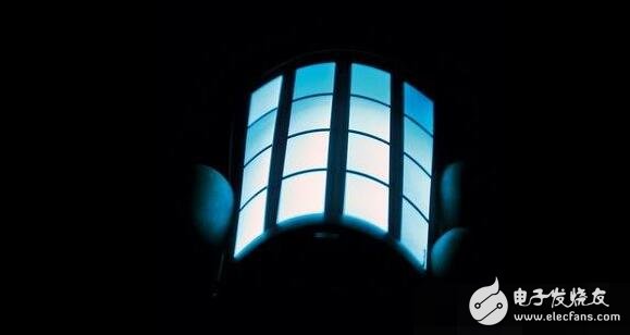
Organic light-emitting diodes can be classified into monochrome, colorful and full-color according to color. Among them, the preparation of full-color organic light-emitting diodes is the most difficult; according to the driving method, passive (Passive Matrix, PMOLED) and active (AcTIve Matrix, AMOLED) can be classified. ).
Principle of oled
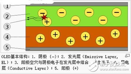
OLED refers to the phenomenon of light emission caused by carrier injection and recombination driven by an electric field. The principle is to use ITO glass transparent electrode and metal electrode as the anode and cathode of the device respectively. Under a certain voltage, electrons and holes are injected from the cathode and the anode to the electron and hole transport layer, respectively, and then migrate to the light-emitting layer respectively. The encounter forms excitons to excite the luminescent molecules, which emit radiation after being irradiated. Radiation light can be observed from the ITO side, and the metal electrode film also acts as a reflective layer.
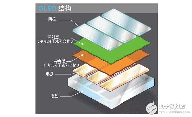
Oled structure
Base layer (transparent plastic, glass, metal foil) - the base layer is used to support the entire OLED.
Anode (transparent) - The anode eliminates electrons (increasing electron "holes") as current flows through the device.
Organic layer - The organic layer is composed of organic molecules or organic polymers.
Conductive layer - This layer consists of organic plastic molecules that carry "holes" from the anode. Polyaniline can be used as the conductive polymer of the OLED.
Emissive layer - This layer consists of organic plastic molecules (different from the conductive layer) that transport electrons from the cathode; the luminescence process takes place at this layer. Polyfluorene can be used as the emissive layer polymer.
The cathode (which may be transparent or opaque, depending on the type of OLED) - the cathode will inject electrons into the circuit when current is flowing through the device.
Oled's illuminating process and principle
OLEDs emit light in a similar way to LEDs, with a process called electrophosphorescence.
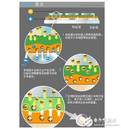
The specific process of OLED illumination is as follows:
1. The battery or power supply of the OLED device will apply a voltage across the OLED.
2. Current flows from the cathode to the anode and through the organic layer (current refers to the flow of electrons).
3. The cathode outputs electrons to the organic molecular emission layer.
4. The anode absorbs electrons from the organic molecular conduction layer. (This can be seen as the anode outputs holes to the conductive layer, and the effects are equal.
5. At the junction of the emissive layer and the conductive layer, electrons will combine with the holes.
6. When an electron encounters a hole, it fills a hole (it will fall into an energy level in the atom of the missing electron).
7. When this process occurs, electrons release energy in the form of photons.
8, OLED lighting.
9. The color of the light depends on the type of organic molecules in the emissive layer. The manufacturer will place several organic films on the same OLED to form a color display.
10. The brightness or intensity of light depends on the amount of current applied. The higher the current, the higher the brightness of the light.
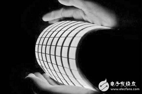
OLED technology can be divided into two main types of small molecules and polymers, and their structures are not the same. However, whether it is a small molecule OLED or a polymer OLED, there is an organic light-emitting material layer between the thin and transparent conductive indium tin oxide (ITO film) cathode and the metal anode - this is similar to a hamburger. Sandwich cake-like structure. This structural layer includes a hole transport layer (HTL), a light-emitting layer (EL), and an electron transport layer (ETL).
Among them, the structure of the yin and yang poles is a standard crystal diode structure, which has unidirectional conductivity and is driven by current at a moderate voltage. The OLED illumination is essentially current driven. When the power is supplied to an appropriate voltage, the positive hole and the cathode charge are combined in the light-emitting layer to produce light, and the three primary colors of red, green, and blue RGB are generated according to the formulation of the light-emitting layer to form a basic color.
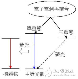
Specifically, when the component is subjected to a forward bias derived from direct current (DC), the applied voltage energy will drive electrons (Electron) and holes (Hole) respectively from the cathode and anode injection components, when both Meeting and bonding in conduction forms a so-called Electro-Hole Capture. - In fact, the real movement is electrons, the filling of holes by electrons can be seen as the movement of holes: this is also the typical way of working with PN junction transistors.
In the process of electron movement, the whole process of electron filling to the hole position is equivalent to the electron obtaining energy (electric energy) and flying away from the original atom, and then being trapped by the hole, and releasing the originally obtained energy (light energy). In this process, if the electron spin (Electron Spin) and the ground state electrons are paired, it is a singlet (Singlet), and the light released is so-called fluorescence (Fluorescence); conversely, if the excited state electron and the ground state electron are self-synchronized Unpolarized and parallel, it is called a triplet, and the light it emits is called Phosphorescence.
Whether in the fluorescent or phosphorescent state, when the state of the electron is returned from the excited high energy level to the steady state low energy level, its energy will be either Light Emission or Heat DissipaTIon (the vibration of the OLED material molecule group). The mode is released, in which part of the photon can be utilized as a display function.
Oled's illumination process can be divided into the following steps: 1. The battery or power supply of the OLED device applies a voltage across the OLED. 2. Current flows from the cathode to the anode and through the organic layer (current refers to the flow of electrons). 3. The cathode outputs electrons to the organic molecular emission layer. 4. The anode absorbs electrons from the organic molecular conduction layer. (This can be considered as the anode outputs holes to the conductive layer, the effect of the two is equal. 5. At the junction of the emissive layer and the conductive layer, electrons will combine with the holes. 6. When the electrons encounter holes, they will fill the holes. (It will fall into an energy level in the atom of the missing electron.) 7. When this process occurs, the electron will release energy in the form of photons. 8. OLED emits light.
Wherein, the color of the light depends on the type of the organic molecules of the emissive layer; the brightness or intensity of the light depends on the magnitude of the applied current. The higher the current, the higher the brightness of the light. OLED molecules rely on the number of pairs of hole electrons received to emit light. A large current means that the number of electrons and holes moving at the same time is large - this is a typical current drive mode.
Rgb Bluetooth Speaker,Rgb Light Bluetooth Speaker,Rgb Portable Speaker For Outdoor,20W Rgb Outdoor Speaker
Comcn Electronics Limited , https://www.comcnspeaker.com