1. Questions raised
A system uses three serial interface sensors (GPS, pressure and wind direction) and three analog current (4-20mA) interface sensors (humidity, temperature and water level). Now we need to aggregate these data and upload them to the PC through the serial port, and require that each signal data can be independently received in real time.
2. System Design
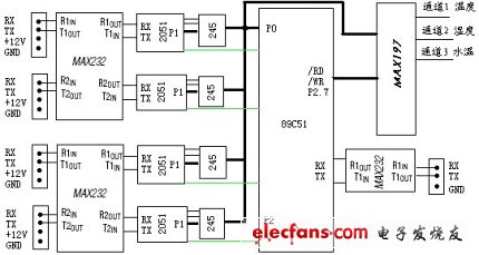
After analysis, we use a 2051 single-chip microcomputer to receive the data of each serial port sensor, and use a multi-channel high-precision ADC to sample the temperature and other signals converted into voltage. The system structure is shown in Figure 1. Refer to Figure 2 for the specific pin connection between the master and slave.

Figure 1 System structure block diagram
The 51 single-chip microcomputer in the system as the host controls the actions of the entire system and initiates each communication. Each block 2051 acts as a real-time acquisition of data from the sensors and completes the communication under the control of the host. The host and each slave communicate through parallel port connection. The master-slave machine workflow is as follows:
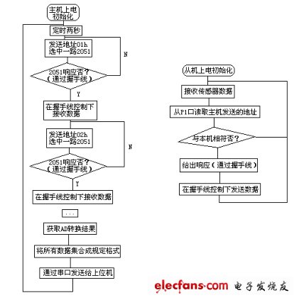
After the host is powered on and initialized, it sends the slave address through the P0 port to select a slave and waits for a response.
Each slave receives the sensor serial data after power-on initialization, and then receives the host address through the P1 port. When the address matches itself, the 245 direction is adjusted and the sensor data is sent from the 245 to the host. This process is controlled by the handshake line.
After sending all the data from the slave, the 245 direction is changed to receive again, and the sensor data and the address sent by the master are restarted.
The host receives all 2051 data in the same way.
After the serial port data is received, the host computer controls AD conversion and obtains three-way signal data.
The host computer gathers all the data into a prescribed format and sends it to the PC via 232.
The working flow chart of the master and slave is shown in Figure 3:

Figure 2 Pin connection between master and slave

Figure 3 Work flow chart of master and slave
High Voltage Lan Transformer,High Voltage Pwoer Pulse Transformer,Cmc Coilfor Automotive Product,High Voltage Pulse Transformer
IHUA INDUSTRIES CO.,LTD. , https://www.ihua-inductor.com