Design and Implementation of Oil Field Wireless Anti-theft Alarm System Based on GSM
An oil field wireless anti-theft alarm system based on GSM network data transmission service and SMS short message service is introduced, and its system structure, working principle, hardware composition, software design, etc. are discussed. The system realizes remote communication of data and real-time monitoring of wellsite terminals.
Keywords: anti-theft alarm; GSM; data service; SMS
Shengyan 110023, China)
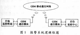
This system adopts the new generation wireless communication GSM module TC35T launched by Siemens, which can quickly, safely and reliably realize data, voice transmission, short message service SMS and fax. Data transmission needs to establish communication and monopolize a wireless channel. Short messages are handled as signaling in the GSM network, and their transmission and reception occupy signaling channels and can be sent separately. As a two-way service, they open up a wide field with high reliability. Therefore, this system has the characteristics of automatic data processing, fast speed, strong anti-interference ability and good compatibility. Due to the use of China's current perfect GSM wireless mobile communication network, the cost of the system and maintenance costs are also greatly reduced, and with the support of relevant software, real-time communication of one point to many points is realized.


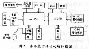
The real-time clock chip adopts DS1302 of American DALLAS company to provide a time reference for the monitoring terminal. The watchdog circuit enables the lower computer to operate according to a certain process under its constraints, prevents system crashes, and enhances the reliability of field work. The wireless remote control receiving unit and hand-held remote control are used for on-site arming or disarming operations. The control output of the system can be various alarm devices such as sound and light alarms, control relays, indicator lights and so on. The TC35T module is mainly composed of a radio frequency antenna, internal FLASH, GSM baseband processor, matching power supply, etc., and is connected to the main CPU serial port of the monitoring terminal through an RS232 interface.
There are three ways for the microprocessor MCU to enter or exit the arming state: (1) according to the instructions of the background monitoring center; (2) the timing of arming or disarming set in the MCU memory; (3) on-site remote control operation commands. After entering the armed state, if the system detects an illegal intrusion signal through an external anti-theft sensor, the system uploads it to the monitoring center and relevant security personnel by data communication or SMS. The monitoring center can carry out remote parameter setting, arming or disarming operations, uploading working status, etc. to the field terminal at any time through the TC35T module.
3.1 Data transmission mode and SMS mode operation of TC35T module TC35T works with AT command set. Before use, a computer must be used to initialize TC35T offline and store the setting parameters in TC35T. The relevant instructions are as follows:
 ?
? After setting, it can be used normally.
In the data communication mode, the "ATD" command is used for call dialing, and the "ATH" command releases all connections. Since the module no longer receives other AT commands in the data communication mode and can only perform data transmission, you need to use "+++" "Command to switch the data mode to the command mode.
For short message mode, TC35T has two access protocols for SMS control: Text Mode based on AT command and PDU Mode based on AT command. In Text Mode, the data sent and received are expressed in ASCII code. In PDU Mode, the text of the short message is transmitted after hex encoding. A PDU is equivalent to a data packet, which is composed of information that constitutes a message (SMS). As a data unit, it must contain the source / destination address, protection (valid) time, data format, protocol type, and text. The text length can be up to 140 bytes, and they are all expressed in hexadecimal. The PDU structure differs according to the short message initiated by the mobile terminal or for the purpose of the mobile terminal. Each message can send 140 bytes. Since the longest data string in this system does not exceed 140 bytes, the data can be sent with one message.
Here is an example to illustrate the sending and receiving of short messages (taking Text Mode as an example):
 ?
? Considering the time-delay problem of GSM transmission, as with the satellite transmission method, both sides only use the self-report method for data transmission and reception. That is: the terminal station uses the self-reporting method to send data to the background center actively, and the background center receives passively; when the background center needs the current data of the terminal station or needs to set the terminal station parameters, the background center only transmits the corresponding Command package, when the terminal station receives this command, it will send the data required by the background center or modify the corresponding parameters in a self-reported manner according to different commands.
3.2 Software design of the lower computer Software design of the terminal of the well site includes the communication program of double MCU, keyboard display program and so on. The two single-chip computers can be connected with a parallel port to read / send data through an interrupt mode; in the usual state, the LED displays the clock.
3.3 PC software design The background monitoring software is developed in VB language under the Windows operating system, which is mainly composed of the monitoring center information management, GSM data and SMS communication function subsystem, and database management three subsystems. It has the functions of menu operation, screen display and sound and light alarm, and the location of the alarm is displayed by electronic map, and a password is set to prevent the system from being maliciously modified or misused.
This system has been applied to an oilfield production company. After nearly a year of operation, good results have been achieved.
To use the 1.25mm Ribbon Connector, you will need to first ensure that the ribbon cable is properly aligned with the connector. The pins on the connector should be lined up with the corresponding holes on the ribbon cable. Once the cable is properly aligned, you can then insert the connector into the corresponding socket on the device.
Overall, the 1.25mm Ribbon Connector is a reliable and versatile connector that is widely used in the electronics industry. Its high-density design and compatibility with ribbon cables make it an ideal choice for many applications
1.25Mm Ribbon Connector,Pressure Terminal Connectors,Pressure Terminal Connector,Pressure Connectors
YUEQING WEIMAI ELECTRONICS CO.,LTD , https://www.weimaiconn.com