In recent years, there are three main types of motors used in electric vehicles in the domestic market: brush motors, position sensor brushless motors, and position sensorless brushless motors. The brushed DC motor is easy to solve the commutation problem, but the noise is large, and the carbon brush is easy to wear or damage, which will increase the difficulty of maintenance and maintenance, increase the use cost; use the sensorless brushless DC motor to easily determine the rotor position, solve the problem Phase problems, but it increases the difficulty of designing, manufacturing and installing the motor, and increases the cost, and the sensor is easily damaged, resulting in shortened service life of the motor; the sensorless brushless DC motor commutation is technically difficult, but It is easier to meet consumer demand in terms of cost and longevity.
This article refers to the address: http://
Based on the above characteristics, the scheme discussed in this paper chooses a sensorless brushless DC motor with high cost performance. The HT46R6 is the main control chip. The back electromotive force is used to realize the normal commutation of the motor. The car drive system works optimally to increase product reliability and service life.
How the system works
The block diagram of the control system is shown in Figure 1. It is mainly composed of MCU, DC brushless motor, LCD liquid crystal display, keyboard, power supply, clock and other modules. The MCU adopts the HT46R6? microprocessor produced by Taiwan Holtek Company, and uses it as the core of the system, together with some peripheral hardware, and cooperates with the software to jointly control the DC brushless motor, thereby achieving the excellent performance of the drive system. For example, the MCU command is used to control the forward and reverse rotation, speed regulation, braking or braking of the motor. According to the number of revolutions of the motor, the stroke is measured and displayed in digital form on the LCD screen. The operation of the keyboard is convenient for viewing the travel and other system information. The power module is mainly used to cut off the corresponding part of the circuit when it is not needed to display, while saving key information to reduce system power consumption.
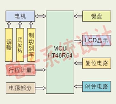
Figure 1: Block diagram of the drive system.
It can be seen from Fig. 1 that the main function of the drive controller is roughly divided into three parts: the motor part, the stroke measurement and the LCD display. This paper mainly focuses on the commutation problem of the sensorless motor.
Back EMF commutation principle
Hall sensors are widely used in motors. The position sensor DC brushless motor relies on Hall sensors to determine the rotor position so that the stator windings are sequentially turned on for commutation, while the sensorless DC brushless machine uses electronic circuits. Instead of the position sensor (Fig. 2), the rotor position is determined by detecting the zero-crossing point of the back EMF generated during the operation of the motor to achieve commutation. The star winding is taken as an example for further explanation.

Figure 2: Block diagram of the sensor structure replaced by an electronic circuit.
The motor has to undergo 6 commutations during operation. Whenever there is a phase winding, there is no energization. At this time, the back electromotive force generated by the winding can be detected at the phase winding port. The back EMF is continuous within 60° electrical angle. of. Due to the difference in the specifications and manufacturing process of the motor, the back EMF values ​​of the same electrical angle are different. If the rotor position is determined by detecting the value of the back EMF, it is very difficult. Therefore, the relationship between the back EMF and the rotor position must be found. Determine the rotor position. It can be seen from Fig. 3 that the back electromotive force always passes through the coordinate horizontal axis (zero crossing point) during the electrical angle of 60°, and the electrical angle here and the electrical angle of the next commutation point are exactly 30°, so it can pass Detect the zero potential of the back EMF and delay the phase shift by 30°. The design is to wait for the counter-potential zero-crossing from the time when the detected phase is powered off, and then wait for the corresponding time to realize the commutation.
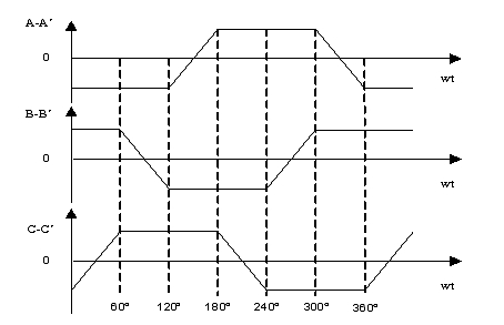
Figure 3: Schematic diagram of the back EMF generated by each phase of the motor.
Take forward anti-potential detection as an example. Suppose that CB is energized before, and the opposite potential of zero is measured. The zero-point signal waits for the corresponding time. The 139 decoder turns on A+, and automatically turns off C+, which is converted into AB power. Then measure the opposite potential of C, use the same method, turn on C-, automatically turn off B-, convert to AC power; then measure B opposite potential, turn on B+, turn off A+, convert to BC energization; then measure A opposite potential, turn on A-, turn off C-, convert to BA power; then measure C opposite potential, turn on C+, turn off B+, convert to CA power; then measure B opposite potential, turn on B-, turn off A-, convert to CB power. After AB→AC→BC→BA→CA→CB six-phase commutation, the continuous forward rotation of DC brushless motor is realized. Similarly, the back-EMF method can be realized by CA→BA→BC→AC→AB→CB six-phase commutation. Continuous reversal of the motor.
2. Back EMF Zero Crossing Scheme
On the basis of the derivation of the position sensorless DC brushless motor model, the method shown in Fig. 4 can be used to detect the zero potential generated by the non-conducting DC brushless motor non-conducting phase winding. The resistor R in Figure 4 acts as a partial voltage. It can be seen that the three-phase voltages of the A, B, and C entering the positive terminal of the comparator LM339 are significantly twice as large as the zero-crossing detection phase (reference phase) voltage. For the star motor winding, The zero point is half of the two-phase energization voltage. After the voltage comparison, the zero signal is sent to the MCU. After receiving the signal, the phase change processing is performed in the program to ensure the normal operation of the motor. The output signal of the LM339 is the so-called motor rotor position signal, which is equivalent to the sensor signal, and essentially sends a commutation notification.
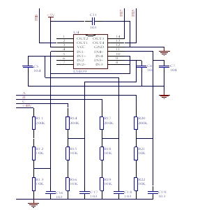
Figure 4: Back EMF Zero Crossing Detection Circuit.
3. Stroke metering and liquid crystal display principle
In this design, the stroke measurement is processed by pure software data. Since the rotor of the electric vehicle motor is outside, the spokes on the vehicle are fixed on the rotor, so that the rotor turns one turn and the wheel turns one turn, and the distance traveled is the circumference of the wheel. In this way, as long as the motor rotates one turn and the internal interrupt is used, the data processing part performs an addition, and the total distance data is stored by the accumulated method, and then the decimal conversion is performed. Since the HT46R6? comes with an LCD driver, you can display the mileage on the LCD screen by simply writing the converted result directly to its RAM memory area 1. The addition of the data processing part uses floating point numbers, because the HT series MCU does not support fractional operations.
System hardware structure
Drive part: The input of the 74HC139 decoder is connected to the HT46R6?, which enables the control bit to be connected to the PWM1 of the HT46R6? (ie, PD1 port). The other inputs are connected to the normal I/O. The output of the decoder directly drives the IR2132. The input of IR2132 is active low to generate the output level to drive the gate of MOS transistor P60N06, plus 48V drain voltage to turn on the MOS transistor. Through this driving method, the MOS transistors are sequentially turned on to give DC The brushless motor is continuously powered. It should be noted that when IR2132 is higher than 8.9V, it can be turned on. Generally, 12V or 15V is used as the driver. The device has undervoltage and overcurrent protection. When the voltage is lower than 8.9V, the IR2132 automatically disconnects and does not work. There is no output and the entire control system will not function properly.
Back EMF section: Using the zero-crossing scheme described in the principle section, the opposite potential voltage is taken through the resistor and sent to the positive terminal of each comparator in the comparator LM339. To reduce the interference, the positive-end input needs to be capacitively filtered. The negative (reference phase) voltage is 1/22 of the 48V power supply. By comparison, if the positive terminal voltage is higher than the negative terminal, the output signal of the LM339 is +5V; if the positive terminal voltage is lower than the negative terminal, the output signal is 0V, thereby giving the rotor position signal, that is, the sensor signal.
LCD part: The design in this article uses a 10-line LCD display with two rows of SEG0-SEG19 and 4 COM pins of the HT46R6?, which can be displayed on the screen by writing to the internal LCD memory area. Simple, intuitive and easy to operate. When R-type bias is selected, no external capacitor or resistor is required. If VDD is greater than the voltage on the VLCD pin, then VMAX is connected to VDD, otherwise it is connected to VLCD. This prevents liquid crystal from being lit due to too strong voltage. The segment selection signal is lit to avoid garbled characters; if C-type bias is selected, a 0.1μF filter capacitor should be connected between V1 and V2 of the microcontroller, and a 0.1μF charge pump capacitor should be connected between C1 and C2. The R-type bias is chosen in this paper. The overall hardware principle is shown in Figure 5.
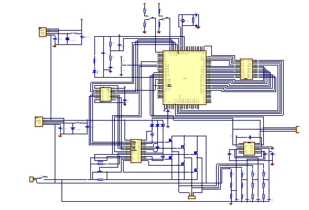
Figure 5: Hardware diagram of the drive controller.
The simulation effect of HT-IDE3000 is excellent, and the PCB board is made as shown in Figure 6 and Figure 7. The main control board and the drive board are connected by jumpers. If time permits, the two boards are usually put together. A heat sink is included.
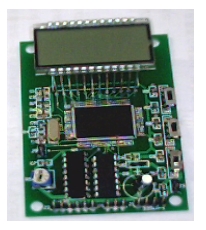
Figure 6: Main control board.
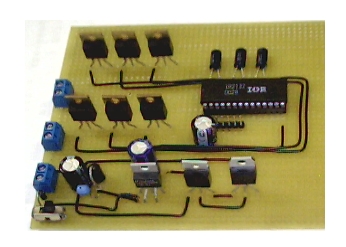
Figure 7: Motor drive board.
System software flow
Turn on the power switch, the program is powered on, and the system enters initialization. The initialization program mainly sets initial values ​​for each control port, including I/O input and output, A/D conversion, PWM control, and interrupt processing. After the initialization is completed, judge whether the control switch is positive or negative. In the non-cruise mode, wait for the vehicle handle (equivalent to a potentiometer) to give a PWM value and start synchronous start at a low speed. If the PWM value is not given, Then it stops at the beginning of the program and the motor does not run.
Once the motor is started synchronously, there will be a back EMF and immediately jump into the back EMF operation phase. At this stage, the motor can be accelerated or decelerated, and the PWM value is given according to the A/D acquisition potentiometer voltage, smooth speed regulation, and no jitter. As we all know, the car handle is made of spring, and the hand will rebound. If it is not controlled, the motor will stop immediately. To solve this problem, the controller has added the cruise function, that is, the PWM value is given to a certain extent, as long as The switch points to the cruise, and the motor is fixed at the speed captured at that time. Even if the switch rebounds, the motor rotates forward or reverse at a fixed speed. Therefore, in the cruise mode, the speed control does not work. When the cruise mode is canceled, it returns to the state where the PWM changes at any time.
Record the number of commutations while the motor is running normally. According to the difference of the number of magnetic poles of the motor, the motor corresponding to the drive system is rotated 10° once, so it is only rotated once for 36 times, that is, the sequence of forward or reverse rotation is to be cycled 6 times. . At this time, an internal interrupt is executed, and the program jumps into the stroke measurement portion to accumulate the circumference of the wheel.
When the floating point number is accumulated, it is judged by the keyboard. If you need to see it, jump to the LCD section and convert the accumulated sum to a decimal number. Here, in kilobytes, keep one decimal place. Then call the LCD display subroutine, and use the lookup table to write the conversion result to the RAM storage area 1 of the HT46R6? MCU, the mileage can be displayed on the LCD screen, and then the interrupt returns to the main program. If you do not need to view the itinerary, you will return to the main program directly after the accumulation is completed.
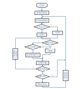
Figure 8: System program flow chart.
Note that in the main program of the controller in this article, the two parts of the program are completely symmetrical, just forward the metering stroke, and the inversion does not, there is no difference in other details. The system software flow is shown in Figure 8, where the back EMF module flow is shown in Figure 9.
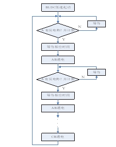
Figure 9: Flow chart of the back EMF program.
Summary of this article
Experiments prove that the design of the drive control system is feasible. The back-EMF detection commutation is normal, the stepless speed regulation system is smooth, and there is a cruise function; the brakes are timely and the brakes are soft, and the basic control of the sensorless DC brushless motor can be realized. The stroke measurement is accumulated by floating point numbers, and the result is displayed on the LCD, which is simple and intuitive. The controller is low in cost, simple in operation and high in reliability. Although this design has made some progress in BLDC back EMF control, the function still needs to be perfected. The IR2132 needs to set the overcurrent value through the resistor shunt. When an abnormal situation is encountered, it is judged whether the circuit is cut off according to the overcurrent value; The back EMF value is small, and the commutation signal may not be obtained by the comparator. If the fixed voltage of the reference terminal is made variable, the speed adjustment range may be increased.
Ningbo Autrends International Trade Co.,Ltd. , https://www.ecigarettevapepods.com