The introduction of high-performance, low-power embedded CPUs and high-reliability network operating systems has made it possible to implement applications such as video telephony, video conferencing, and remote video surveillance in embedded devices. The traditional coaxial cable-based video surveillance system has complex structure, poor stability, low reliability and high price. Therefore, a remote web video surveillance system such as an embedded network video server has appeared. In the embedded wireless video surveillance system, a high-performance ARM9 chip is used as a microprocessor to control video4linux to realize USB camera video data acquisition, and the captured video data is compressed by JPEG, and transmitted under 2.4 GHz wireless control under the control of ARM9 chip/ The receiving module performs video data transmission; the video transmission module submits the video data to the video application server through the serial port or the network, and finally the video application server reassembles and combines the received compressed data frames into video images to implement wireless video monitoring.
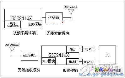
1 system compositionThe whole system consists of five modules: video capture terminal, 2.4G wireless transmission module, 2.4G wireless receiving module, video transmission and video application server. Its composition is shown in Figure 1:

Figure 1 Block diagram of embedded wireless video surveillance system
The video capture terminal includes a central control and data processing center with S3C2410X as the core and a USB Camera data acquisition unit. The central control and data processing center mainly completes video capture terminal control and video image compression, and encodes the data to be transmitted, and then sends it to the nRF2401 wireless transmission module through SIO.
The video transmission module mainly includes: a central control and data processing center with S3C2410X as the core and a MAC interface and a UART interface for transmitting video data to the video application server. The central control and data processing center of the video transmission module mainly accomplishes the following tasks: nRF2401 submits the received video data to the SIO module, and the S3C2410X first decodes the SIO module data, and then transmits the video data to the video application server through the UART interface or the MAC interface. .
The video application server receives video data from a serial port or a network interface, and reassembles and composites it into a video image.
1.1 Video capture terminal hardware structure
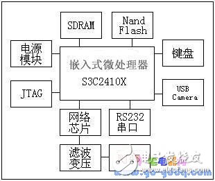
In this design, the S3C2410X inherits the on-chip resources, and only needs to expand the SDRAM, Nand Flash, 4X4 Array Keyboard, USB Host, Ethernet Interface, RS232 Interface, JTAG, Power and other modules. The video capture terminal is one of the core modules of the whole system, mainly completing video capture and image compression. The hardware logic block diagram is shown in Figure 2:

Figure 2 video acquisition terminal hardware logic block diagram
2 Video acquisition module design and implementationThe video capture module is the core of the entire video capture terminal. It uses the embedded Linux operating system to schedule V4L (video4linux) and imaging device drivers for video capture. V4L is the basis of Linux imaging system and embedded image. It is a set of APIs supporting image devices in Linux kernel. With appropriate video capture card and video capture card driver, V4L can realize image acquisition, AM/FM wireless broadcast, and video. CODEC, channel switching and other functions. At present, V4L is mainly used in video streaming systems and embedded imaging systems, and its application range is quite wide, such as: distance learning, telemedicine, video conferencing, video surveillance, video telephony, etc. V4L is a 2-layer architecture with the V4L driver at the top and the imaging device driver at the bottom.
In the Linux operating system, external devices are managed as device files, and therefore operations on external devices are converted into operations on device files. The video device file is located in the /dev/ directory, which is usually video0. When the camera is connected to the video capture terminal through the USB interface, the video data acquisition of the camera can be realized by calling the V4L APIs to read the device file video0 in the program. The main process is as follows:
1) Open the device file: int v4l_open(char *dev, v4l_devICe *vd){}Open the device file of the image source;
2) Initialize picture: int v4l_get_picture(v4l_device *vd){} to get the input image information;
3) Initialize channel:int v4l_get_channels(v4l_device *vd){} Get the information of each channel;
4) Set the norm:int v4l_set_norm(v4l_device *vd, int norm){} to the channel to set norm for all channels;
5) Device address mapping: v4l_mmap_init(v4l_device *vd){} returns the address where the image data is stored;
6) Initialize the mmap buffer: int v4l_grab_init(v4l_device *vd, int width, int height){};
7) Video capture sync: int v4l_grab_sync(v4l_device *vd){};
8) Video capture: int device_grab_frame(){}.
Through the above operations, the camera video data can be collected into the memory. The video data collected into the memory can be saved in the form of a file, or it can be compressed and encapsulated into a data packet and transmitted to the data processing center through the network. This design adopts the latter processing method, that is, the captured video data is first JPEG-compressed, and then encapsulated into a data packet and transmitted to the video application server for processing.
Indoor Cable,Indoor Fiber Optic Cable,Indoor Fiber Cable,Indoor Optical Fiber Cable
Huizhou Fibercan Industrial Co.Ltd , https://www.fibercannetworks.com