The spraying robot, also called spray painTIng robot, is an industrial robot that can automatically paint or spray other coatings. It was invented in 1969 by Norwegian Trallfa (later incorporated into ABB Group). The painting robot is mainly composed of a robot body, a computer and a corresponding control system. The hydraulically driven painting robot also includes a hydraulic oil source such as an oil pump, a fuel tank and a motor. More than 5 or 6 degrees of freedom joint structure, the arm has a large movement space, and can do complex trajectory movement, the wrist generally has 2 to 3 degrees of freedom, flexible movement. The more advanced painting robot wrist uses a flexible wrist that can be bent and rotated in all directions. Its action is similar to that of a human wrist. It can easily penetrate into the inside of the workpiece through a small hole and spray the inner surface. The painting robot is generally driven by hydraulic pressure, and has the characteristics of fast action speed and good explosion-proof performance. It can be taught by hand teaching or point display. Painting robots are widely used in the production of automotive, instrumentation, electrical appliances, enamel and other processes.
The main advantages of the painting robot(1) Flexible. The scope of work is large.
(2) Improve the quality of the spray and the rate of material use.
(3) Easy to operate and maintain. Can be programmed offline, greatly reducing on-site debugging time.
(4) High equipment utilization. The utilization rate of the painting robot can reach 90%-95%.
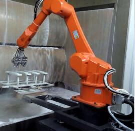
1. The automatic spraying robot is sprayed on the air spray gun and the electrostatic rotating cup. The spraying parameters such as the paint discharge amount, the atomization control air pressure and the spray width control air pressure can be directly modified by the robot, which greatly improves the efficiency of controlling the spraying process.
2. The automatic spraying robot controller is a robot controller designed from the aspects of safety, reliability and efficiency. The internal modular design makes function upgrades and maintenance easier. For spray applications, there is an independent air purification control module inside, and the teach pendant is also explosion-proof.
3, automatic spraying robot spraying control cabinet, through the standard analog output module to control the discharge parameters, spray width, atomization and other spray parameters.
4 Automatic spray robot closed-loop control The delivery system automatically adjusts the flow to provide a stable flow and optimum final quality. The integrated fretting color changer reduces color change time and reduces waste.
5. The software designed by the automatic spraying robot for the spraying application can be flexibly called in the working program. The preset spray parameters include paint discharge amount, atomization control air pressure, and spray width control air pressure. With this feature, you can test the online tracking program without actually running the transfer chain, thus improving the efficiency of teaching.
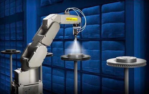
1, the main body of the robot
The main body of the robot, the base, the arm, the wrist and the terminal actuator, is a series of mechanical linkages with a 6-axis or 7-axis linkage with a rotary connection and an AC servo motor (see Figure 5), using the gear train (gear Drive chain) and RV (rotation vector) type reducer. Most spray robots have 3 to 6 degrees of freedom of motion (for a tracked robot, the horizontal movement of the robot body on the track is generally set to the extended axis, called the 7th axis). The wrist usually has 1 to 3 degrees of freedom of movement.
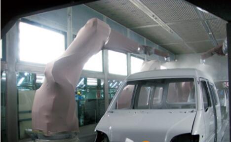
The drive system includes a power unit and a transmission mechanism for causing the actuator to generate a corresponding action, that is, the movement of each shaft is controlled by a servo motor driven transmission mechanism mounted in the robot arm. The actuator is an electrostatic spray atomizer. The interfaces of the end of the robot arm of different brands and different models are different. Different atomizers can be selected according to the production process.
For systems using solvent-based paint spraying, waste paint waste solvent cleaning and recovery devices must be equipped to avoid environmental pollution and achieve environmentally friendly production.
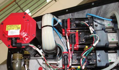
2, the robot controller
Each robotic device can operate independently, and the robot controller ("RC") is a device that commands the drive system and the actuator according to the input program to control the motion track of a single robot device. The main components in the controller are the servo amplifier and CPU module connected to the servo motor in the robot arm (see Figure 6). Different models of robots are equipped with different memory CPUs, and the CPU stores user-defined data and programs. The CPU converts the program data into a servo drive signal to the servo amplifier, and the servo amplifier activates the servo motor to control the motion of the robot. Usually, the CPU module also has the function of communicating with other external devices or robots by connecting with different types of I/O modules. For example, the connection to the PLC, so that the action of the robot can be controlled by operating the console. Generally, one controller independently controls one robot. With the development of technology and the process of low cost, a device that controls the movement of two robots at the same time has appeared.
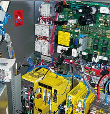
The robot teach pendant is connected to the CPU in the robot controller through a single cable. Different application software is installed in the teaching device of different brand robots, and the functions are also different. The menus on the software interface are operated by buttons on the teach pendant panel. The main functions that can be implemented are: direct programming, displaying user programs, manipulating robot movements, pre-defined robot positions, optimizing user-defined programs, and editing system variables.
3, system operation console
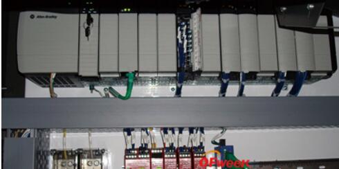
The main function of the System Operation Console ("SCC") is to integrate the entire spray booth hardware to implement system automation functions, including all the hardware related to the management of the painting robot activities and the related hardware integrated into each spray booth. For example, safety interlock relays, isolation gratings, etc. associated with the spray booth system. A programmable logic controller PLC (see Figure 7) is installed in the cabinet. The above hardware communicates with the PLC through various types of I/O modules. The PLC receives the real-time signals of each robot and system unit peripherals in the spray booth unit through the I/O module, including data exchange with the factory main information system and other robot system units, and then according to the pre-programmed logic judgment program. The received signals are collected for corresponding processing and the resulting variables are sent to the relevant systems. Another main function of SCC is to provide a friendly operation interface to realize human-computer interaction, so that the whole system can work continuously and in an orderly and stable manner according to people's wishes under human supervision. Generally, the human-computer graphics interactive system, that is, a computer host and a display are integrated into the system operation console, and the computer host is connected to the PLC through various upper-level control networks. Different manufacturers' human-computer graphics interactive system is equipped with different user softwares. The man-machine interface of the software displays the real-time status of the robot system and the user operation menu in the entire area, and can search related production information and alarms. Most of the device operations can be done by operating a button on the SCC or a selection switch and a menu on the human interface.
4, process control cabinet
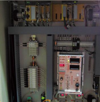
The main purpose of applying automatic spray robots is to apply different types and colors of paint to the surface of the vehicle evenly through the movement of the robot. The process control cabinet ("PCE") is the electrical signal and the potential volatile paint and A relatively safe interface between solvents that converts electrical signals into pneumatic signals. The internal components of the PCE cabinet are shown in Figure 8. The electrical signal from the PLC triggers the solenoid valve in the PCE cabinet, opens the air (or vacuum) circuit, and drives the pneumatic valve on each paint or solvent line interface through a certain air pressure. Paints or solvents of different colors are supplied to the robot for spraying or cleaning the pipeline. The main function of PCE is to control various actions of the spraying process, such as color change and cleaning. Control various process parameters such as paint flow rate, atomizer rotor speed and so on. With the continuous development of robot technology, most of the brand's painting robot systems use a closed-loop flow control system to accurately control the actual output flow of paint or solvent by installing a flow meter or metering pump on the robot arm close to the end effector. The error between the value and the set value. Different types of robot system structures may be designed to integrate the functional components of this PCE into other system spaces instead of forming a single process control cabinet, which can save the production site resources and beautify the production environment.
5, model detection system
The automatic painting robot has a strong flexible production capacity and can spray a variety of different shapes of the body at the same time. For reasons of protection system, it is necessary to test the type of body before the body enters the robot spray booth. Generally, a plurality of pairs of photoelectric switches are installed in front of the wiping function area, and a proximity switch is installed on the conveyor chain base frame about 1 m from the nearest pair of photoelectric switches. According to the difference between different production sites and the models produced, different positions are set by the PLC program as the detection position, and the installation position of the photoelectric switch is adjusted. When the body that is about to enter the spray booth reaches the detection position, different models will trigger different combinations of electronic eyes to detect whether the vehicle information from the factory information system is consistent with the vehicle type detected by the vehicle detection system. If they are inconsistent, the system will To generate an alarm and stop running, the operator must manually confirm the model and input the correct vehicle information on the corresponding interface of the SCC. The PLC then sends the correct vehicle information to the CPU module in each robot controller. Converted into various instructions, the robot executes different programs according to this instruction, achieving the purpose of performing different spray trajectories according to different vehicle models.
Note that the transmitting and receiving ends of two adjacent pairs of electronic eyes should be staggered to avoid generating error messages.
6, set up a safe, isolated production area
Since the robotic equipment is continuously operated during the normal production process, it must be strictly isolated from the artificial area to prevent any personal injury accidents and achieve safe production. Usually, a pair of safety gratings can be respectively installed at the entrance and exit of the automatic spraying area of ​​the robot. In the production process, if someone accidentally breaks into the automatic spraying area of ​​the robot, the grating is triggered at the position where the grating is installed, and the system generates a corresponding alarm. And immediately stop running to prevent accidents of personal injury and damage to equipment. However, since the body must also enter the automatic spray area through the area where the safety grating is installed, the grating is also triggered during this process. In order to solve this contradictory problem, a switch for shielding the safety grating can be installed on the side of the conveyor chain base before the position where the safety grating is installed. When the body of the transport body runs to the switch, the switch is triggered to give the system PLC a Signal, this signal is used to shield the safety grating. In order to ensure a more strict distinction between the person or the body entering the automatic spraying area, it is better to install a shielding switch on each side of the conveyor chain base frame, and only two switches are triggered to function as a shielding safety grating. If someone mistakes and does not trigger the shielding switch at both ends, the safety grating is still in working state, and the safety grating will still be triggered when the person is in the position of the safety grating.
7, body linear tracking system
The robot used in the automatic spraying line of the whole vehicle, in order to improve the production cycle, the body always follows the conveyor chain according to the set speed during the spraying operation, and does not leave the conveyor chain fixed somewhere for the robot spraying operation. Therefore, each robot must know the real-time position information of each body in the working range. The hardware of the linear tracking system mainly includes: a pulse encoder, a detection switch and an encoder transponder. According to the user's preference, different detection switches can be selected, which can be contact switches or optical switches, or proximity switches. When the vehicle body moves to the position of the detection switch with the ground conveyor chain, the detection switch is triggered, and the pulse encoder starts counting. Calculate the real-time position of the body. The input shaft of the pulse encoder is mechanically coupled to the central axis of the ground conveyor chain to obtain synchronization information for the movement of the conveyor chain. The output shaft is connected to the encoder transponder. The encoder transponder is integrated into the SCC cabinet, and the real-time position information of the vehicle body can be sent to the PLC and each robot controller through the encoder transponder.
8, power distribution cabinet
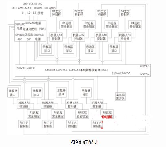
The power distribution cabinet, as the name suggests, is the distribution source. The total power supply of the plant is introduced, and the power supply of the corresponding voltage and current value is allocated according to the power supply value required by the robot system unit and the peripheral device. You can choose a standard universal EDS power distribution cabinet, or you can design a non-standard power distribution cabinet according to user needs. The system configuration is shown in Figure 9.
Many people do not know what kind of cameras are invisible cameras, and do not know how to distinguish invisible cameras, so here is how to distinguish invisible cameras.
Invisibility, as the name suggests, means that it is not easy to be seen or found, so where do such cameras exist? In fact, invisible things are hidden by the external environment, so they will not be discovered. Such invisible cameras are generally hidden in things that are more difficult to see, such as: inside the socket, inside the TV, inside the stereo, inside the fan, etc. Cameras can be hidden in various household appliances. Why should they be hidden in electrical equipment? The main reason is that these equipments have power supply and will not be used because the camera cannot be powered.
USB Charger Camera,HD 1080P Camera,HD 720P Camera,4K Camera,Night Vision Camera,wifi Camera
Jingjiang Gisen Technology Co.,Ltd , https://www.jsgisengroup.com