0 Preface
At present, DALLAS's digital temperature sensor DS18B20 is widely used in multi-point temperature measurement systems. The advantage is that only one bus can complete the exchange and control of data in the system. However, the DS18B20 has a slow response speed and low accuracy. In actual applications, when the number of bus-attached DS18B20s exceeds 8, it is necessary to provide independent power supply for each DS18B20, which makes system maintenance difficult. Infrared temperature measurement technology as a convenience. Accurate non-contact temperature measurement technology has been rapidly developed. Infrared temperature measurement allows continuous access to difficult-to-reach areas or hazardous areas within its field of view. Real-time temperature monitoring effectively reduces the risk factor of temperature measurement operations; and has a small volume. High precision. Networkable and real-time performance and other advantages. In this paper, the digital infrared temperature sensor MLX90615 is used as the temperature detecting device, and the STM32 microprocessor is used as the core to design and implement the multi-point infrared temperature measuring system.
The system has the advantages of high temperature measurement accuracy; measurement does not affect the distribution of temperature field; non-contact temperature measurement reduces the risk factor; short response time, easy to achieve dynamic measurement.
1 Basic principle of infrared radiation temperature measurement
Infrared radiation is a kind of light that is invisible to the human eye. It is commonly called infrared light. It is the light between red light and microwave in visible light. Due to the movement of charged particles, all objects with temperatures above absolute zero are constantly emitting infrared radiation energy to the surrounding space. The energy wavelength is mainly concentrated in the 0.6~15 μm band. The relationship between radiant energy density and temperature is in accordance with Stephen Boltzmann's law of radiation:

It can be known from the formula (1) that the radiation power emitted by the object can be calculated as long as the temperature of the object and its radiance are known. Conversely, if the radiant power of the object is measured, the temperature of the object can be determined. The output signal of the infrared sensor is the result of the interaction between the measured target temperature To and the sensor's own temperature Ta:
Where: the temperature unit is Kelvin; A is the instrument constant, which is related to the design structure of the sensor.
2 hardware design
The hardware part of the non-contact multi-point infrared temperature measurement system is mainly composed of an infrared sensor group. microprocessor. It consists of other peripheral circuits and PCs. The infrared sensor converts the infrared radiation in the field of view into a digital signal, and transmits the data to the STM32 microprocessor through the SMBus bus. The microprocessor communicates with the host computer for serial communication, and displays the temperature data on the host computer.
2.1 Infrared sensor section
The sensor part uses the digital infrared sensor MLX90615ESG-DAA, which is a high-precision digital temperature measurement chip produced by Melexis. It has two output modes of PWM and SMBus. The normal working temperature range is -40~85 °C. The temperature range of the measuring object is -40~115 °C. If a smaller temperature range is required, the corresponding control word in the E2PROM can be modified by the SMBus bus to change this range, thereby improving the accuracy. The emissivity can be set to any value between 0 and 1.0, according to the formula:
Emissivity = dec2hex[round(16 384&TImes;ε)] converts any floating point ε between 0 and 1.0 into a hexadecimal number and then writes the corresponding control word.
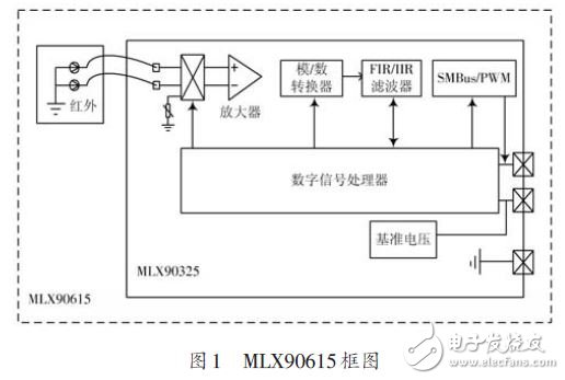
The MLX90615 is mainly composed of an infrared thermopile sensor, a low noise amplifier, a 16-bit analog-to-digital converter, and a DSP unit. The block diagram of the structure is shown in Figure 1. The infrared thermopile sensor converts the collected infrared radiation into an electrical signal, which is amplified by a low noise amplifier and sent to an analog/digital converter. The digital signal output by the analog-to-digital converter is processed by the FIR/IIR low-pass filter and sent to the digital signal processor. The digital signal processor processes the digital signal and outputs the measurement result and saves it in the internal RAM of the MLX90615, which can be passed through SMBus or The PWM mode is read by the master CPU unit.

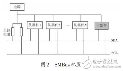
Several infrared sensors are used as slaves to connect to the microprocessor via the SMBus bus. A typical SMBus configuration is shown in Figure 2 [3]. Both the SDA and SCL pins require a weak pull-up of 300 kΩ. Note that the MLX90615 infrared sensor supports a 7-bit address, so the maximum number of sensors on the same bus is 127.

2.2 Microprocessor
The microprocessor uses the ARM Cortex-M3-based 32-bit microcontroller STM32F103C8T6. The microprocessor is highly reliable and reliable. Wide temperature range, abundant resources, low power consumption, etc., widely used in medical care, handheld devices, motor control and other occasions. STM32F103C8T6 has 64 KB of on-chip FLASH memory, 32 general-purpose I/O pins, two 10-channel 12-bit A/D converters, three general-purpose timers and other peripheral resources and communication with USART, I2C, SPI, CAN, etc. The interface can meet the design requirements of the multi-point infrared temperature measurement system.
3 software design
3.1 MLX90615 transmission protocol
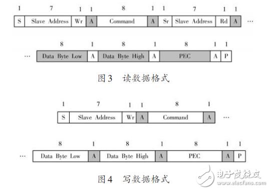
The SMBus data transfer protocol provides the possibility of data communication between the master device and the slave device. The protocol stipulates that only one master device can be active on the bus at a time. The master device can “communicate†with the slave device through “read data†and “write dataâ€. The data transmission format is shown in Figure 3 and Figure 4. Where S is the start bit, Slave Address is the slave address, Wr is the write flag, Command is the command byte, Rd is the read flag, PEC is the error packet, and P is the stop bit.

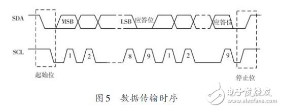
The data on SDA can be changed after SCL goes low for 300 ns, and data is captured on the rising edge of SCL. The 16-bit data is transmitted twice, one byte at a time. Each byte is transmitted in the format of the high order (MSB) first and the low order (LSB), and the ninth clock between the two bytes is the acknowledge clock. The data transmission timing is shown in Figure 5.

EASY TO ATTACH - These bright Bicycle Lights are easy to attach on/remove of any vehicle. During the week use them on your city bike while in the weekend you can go cruising on your mountain bike
LONG LIFE QUALITY - This simple but efficient design is made of high quality waterproof silicon for a longer lifespan. The premium quality material used will protect them from damaging quickly!
VISIBILITY FOR SAFETY - Bicycle Lights are very bright, making you visible to others. Plus they provide you with a view on obstacles that lay ahead. Creating safety during your nightly escapades!
SATISFACTION GUARANTEED - We Provide High Quality Products. Our team is always ready to help you get the most out of your product accessories. 100% Satisfaction Guaranteed!
Bicycle Lights
Bicycle Lights,Magnet Bicycle Flashlight,Front Light,Rear Light
Ningbo Henglang Import & Export Co.,Ltd , https://www.odistarflashlight.com