Abstract: Multiple series inverters have many advantages in electric vehicles. The series structure output voltage vector type is greatly increased, which enhances the control flexibility, improves the control accuracy, and reduces the fluctuation of the neutral point voltage of the motor. The bypass feature of the inverter increases the flexibility of charging and regenerative braking control.
This article refers to the address: http://
Key words: electric vehicle; series inverter; inverter bypass
Application of Cascaded Inverter to Electric Vehicle
SHAN Qing-xiao, HU Kai, YU Zhi-xong
Abstract: The application of cascaded inverter to electric vehicle can improve control freedom and accuracy by increasing number of output vector. And the voltage ripple of motor common end is also reduced. Bypass mode of single inverter is applied to increase control effect of charge and regenerative Brake.
Keywords:Electric vehicle; Cascaded inverter; Bypass mode of inverter
1 Overview
With the growing concern about the urban environment, the development of electric vehicles has a rare opportunity. In urban traffic, electric buses have become a priority for development due to their large load and high overall efficiency. Most electric buses use three-phase AC motors. Due to the high power of the motor, the components in the three-phase inverter need to withstand high voltage and high current stress. The higher dv/dt makes the electromagnetic radiation serious and needs good. Cooling.
The high-power inverter with multiple series structure reduces the voltage stress on a single device and reduces the requirements on the device; reduces the dv/dt value, reduces the electromagnetic radiation, and greatly reduces the heat generation of the device; The level of the level is increased and the control performance is better.
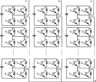
Figure 1 shows a three-phase inverter in multiple series. Each unit inverter is a single-phase full-bridge inverter with an independent DC power supply. On an electric vehicle, it is supplied by a separate battery. Therefore, the danger caused by the series connection of a plurality of batteries is reduced, and the disassembly of the battery is facilitated.

Figure 1 Multiple series three-phase inverter
2 multiple series structure
Let m unit inverters be connected in series. If the battery voltage of the DC side of each unit inverter is the same, the number of levels that can be combined is m; if the battery voltage of each unit inverter is different, the combined power The number of flats will increase greatly. The inverter is composed of two unit inverters with battery voltages Va and Vb (Va>Vb), and the positive levels that can be output are Va+Vb, Va, Va-Vb, Vb. If Va = Vb, the number of positive levels is 2; if Va ≠Vb, and Va - Vb ≠Vb, the number of positive levels is 4. It can be seen that the type of the output level can be increased by appropriately selecting the voltage ratio. The following analysis assumes that the battery voltages are equal.
3 multiple series inverter
3.1 The complex expression of the output vector
Compared with the three-phase SPWM technology, the control method of the multiple series inverter has multi-harmonic PWM technology (SHPWM) [1], phase shift PWM technology (PSPWM) [2] and so on. Since the dynamic response of the electric vehicle to the motor has high requirements, the electric vehicle adopting the three-phase asynchronous motor generally adopts a vector control method and a direct torque control method. In the vector control, since the multiple series inverter can output a variety of PWM levels, the number of switching can be greatly reduced in the current tracking control, the harmonics of the output current can be reduced, and the tracking effect can be improved.
When space vector control is used, the inverter output vector can be expressed as follows:
v(t)= ![]() [vaN(t)+a·vbN(t)+a2·vcN(t)](1)
[vaN(t)+a·vbN(t)+a2·vcN(t)](1)
Where: vaN, vbN, vcN are the voltages of the output terminals A, B, C relative to the neutral point N.
a= ![]() .
.
Assume
v(t)=vx+i·vy
then
Vx= ![]() (2·vaN-vbN-vcN) (2)
(2·vaN-vbN-vcN) (2)
Vy= ![]() ·(vbN-vcN) (3)
·(vbN-vcN) (3)
3.2 Several states of the unit inverter
In a multiple series configuration, each unit inverter has three states: forward conduction, reverse conduction, and bypass. As shown in Figure 2, when S11, S14 are turned on, the inverter is in "positive conduction", and the forward voltage is output; when S12, S13 are turned on, the inverter is in "reverse conduction", and the reverse voltage is output; When the arm is fully open or the lower arm is fully open, the inverter is in the "bypass" state and no voltage is output.

(a) Positive guidance (b) Reverse guidance

(c) Bypass state 1 (d) Bypass state 2
Figure 2 Several states of a single inverter bridge
Set the state function of the unit inverter
Fi= ![]()
Taking phase A as an example, suppose phase A consists of m unit inverters connected in series. The neutral point voltage is constant, then the phase A output voltage is
vaN= ![]() fiVi
fiVi
Where: Vi is the ith unit inverter battery voltage.
For the three-phase n-rear series inverter bridge, it can be seen from the above analysis that each phase can output 2n kinds of voltages, and the number of spatial voltage vectors that can be combined by the three phases is 8n3. Considering that the output vector must maintain the stability of the neutral point voltage, the number of possible space vector types in the static coordinate system is 3(2n)(2n-1)+1[3]. For a three-phase double series inverter bridge, the number of space vectors can be selected to be 37.
3.3 Switch combination selection
The block diagram of the multiple inverter bridge switch combination is shown in Figure 3.

Figure 3 Multiple inverter bridge switch combination selection
Since multiple inverters have a switch redundancy state, that is, for the same space vector, it can be realized by a combination of multiple switches, which is determined by the characteristics of multiple inverters. Since the switch combination is no longer unique, in order to make the operating frequency of each switching device equal, after selecting the space vector, it is necessary to perform switching frequency equalization control and select an appropriate switch combination.
4 Neutral point offset
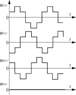
For the two-level three-phase inverter shown in Figure 4, the voltage of N' is used as the reference voltage, then UN'= ![]() The voltage at the neutral point N is pulsating, the pulsation amplitude is Ud/6, and the waveform is as shown in Fig. 5 [3]. For multiple inverters, there are many levels of output. Take the double inverter as an example. Assume that the DC side voltage of each unit inverter is Ud, and the output uUN', uVN', uWN' is the ladder. Wave, the level of the step wave is Ud, 2Ud, as shown in Figure 6. Let uN=Ud, by
The voltage at the neutral point N is pulsating, the pulsation amplitude is Ud/6, and the waveform is as shown in Fig. 5 [3]. For multiple inverters, there are many levels of output. Take the double inverter as an example. Assume that the DC side voltage of each unit inverter is Ud, and the output uUN', uVN', uWN' is the ladder. Wave, the level of the step wave is Ud, 2Ud, as shown in Figure 6. Let uN=Ud, by
uNN'= ![]() (uUN'+uVN'+uWN') (4)
(uUN'+uVN'+uWN') (4)
Available uNN'=0

Figure 4 three-phase voltage bridge circuit

Figure 5 Voltage waveform of neutral point N

Figure 6 voltage waveform of the output of the double inverter bridge
It can be seen that during the operation of the double inverter bridge, the voltage of the neutral point N can be kept constant by appropriately selecting the output vector.
5 Balanced charge and discharge of the battery
Since the operating conditions of electric vehicles vary with driving conditions, the voltage of the motor is also fluctuating at any time. For multiple inverters, not all batteries are involved in the supply of current. At low modulation factors, only a few batteries contribute current. This part of the battery discharges faster than other batteries.
In order to balance the discharge of the battery, it has been proposed to use an alternating conduction method to equalize the discharge of the battery [4]. When this method is used in a two-inverter, the switching waveform is assigned as shown in Figure 7.

Figure 7: Double-inverter uses alternating conduction to equalize the discharge of the battery.
When charging and regenerative braking, the multi-inverter operates as a rectifier. When the upper arm or the lower arm is fully turned on per unit inverter, the battery pack of the inverter is bypassed. Set n inverter bridges in series, and i inverters are bypassed, then the output voltage is (n-i)Ud. By means of bypass, the battery pack can be flexibly charged and the torque of regenerative braking can be controlled.
6 Conclusion
Multiple series inverters are suitable for high power electric vehicle drive systems. The use of multiple series structure reduces the risk of multiple batteries in series, reducing the switching stress of the device and reducing electromagnetic radiation. But the number of batteries needed has increased by a factor of two.
The multiple series structure output voltage vector type is greatly increased, thereby enhancing the control flexibility, improving the control accuracy, and reducing the fluctuation of the neutral point voltage of the motor. In order to maintain the balance of the battery capacity of each group, it is necessary to ensure that the discharge time of the battery is consistent during operation. By means of bypass, the battery pack can be flexibly charged and the torque of regenerative braking can be controlled.
IPhone Battery Case designed not only a phone cover but also a new upgrade large capacity Power Bank,but it`s more light and thin than power bank with large and real capacity. Integrated with ultra thin and light design, faster charging battery charging protection,smart output voltage, thisIphone Battery Case makes you life more relaxed.Smart chip is adopted for stable and quicker charging, it can adapt to current intelligently and will not be burned when charging. It also can charge for the device and transform date in the same time.


Iphone X Battery Case ,Iphone Xsmart Battery Case,Apple Iphone X Battery Case,Best Iphone X Battery Case
Shenzhen Hequanqingnuo Electronic Technology Co., Ltd. , http://www.hqqnbattery.com