Summary
This article refers to the address: http://
Compared to traditional optocouplers, Avago's new ACE Q100 optocouplers, the ACPL-K4xT / ACPL-K7xT series, have significantly lower LED drive currents, reducing system power consumption. In addition, the unique extended surface mount kit reduces the pin and volume of the optocoupler while increasing the insulation gap and creepage distance, thereby increasing the rated insulation voltage. The ACPL-K4xT//K7xT series of digital optocouplers are widely used in IPM drivers, CAN bus interfaces, and discrete digital signal isolation in HEV, PHEV, and EV systems.
Introduction
Due to the increasing number of electronic and electrical components used in automotive systems, systems are made more susceptible to transient circuits and short circuits, so additional protection must be taken to prevent damage to critical systems. This is especially important when an electric motor drives a hybrid or all-electric vehicle. In this case, a high voltage of up to several hundred volts may be introduced into the power system. In addition, in addition to high-voltage power conversion, data communication subsystems such as CAN (Control Area Network) networks must also be protected so that high voltages cannot pass through the ECU (engine control unit), BMS (battery management system), and temperature. Other subsystems such as control systems. Some examples of interface circuits are attached to illustrate the principles of how optocouplers are applied in these areas.
High reliability
After more than 35 years of improvement, LEDs have created a strong advantage with exquisite manufacturing processes. Avago leverages this experience to provide highly reliable LED optocouplers for a wide range of applications in industrial, military and space applications. The key to reliability is the LED processing technology developed by Avago to achieve automotive ACE Q100 performance.
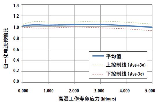
The Avago optocoupler passed the stress test at a temperature of 150 ° C and an LED drive current of 20 mA. The current transfer ratio (CTR) parameter is proportional to the LED's light output. The CTR-time diagram, shown in Figure 1 [1], can be used to indirectly measure the degradation rate of an LED over its entire life cycle. As shown in the figure, there is almost no degradation after 5000 hours of stress testing. Based on this measurement, it can be predicted that the working life in automotive applications will last for more than 100 years.

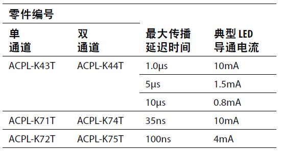
Table 1. Low LED drive current

Figure 1. High performance of LEDs subjected to 5000 hours of stress testing at 150 °C
Low power consumption
In addition to extending the operating life, the Avago digital optocoupler significantly reduces the LED drive current compared to competitive optocouplers (see Table 1). For example, the 1Mbps (non-return-to-zero code) functional ACPL-K43T / ACPL-K44T series optocoupler [2] has three typical rated drive currents: 0.8mA, 1.5mA, and 10mA configurations. In addition, Avago's high-speed CMOS optocoupler series ACPL-K72T/75T requires only 4mA drive level. This relatively low level facilitates system design because no additional current buffer is required to drive the LED directly through the output pin of the microcontroller.
Let's use the ACPL-K43T as an example to explore the real power consumption. The system conditions for determining power consumption are as follows: 50% duty cycle (DC) input LED current is 1.5mA, output pull-up resistor 10kW, output supply voltage is 5V:

Remarks: Pi = input power, Po = output power, IF = LED forward current, VF = LED forward voltage, ICCL = output low current, ICCH = output high current, VCC = output supply voltage.
Extra power is consumed by pull-up resistors:
Extended insulation voltage

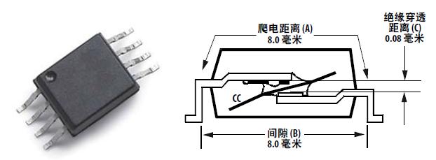
Figure 2. Extended SO-8 package
Electrical safety isolation is the requirement of high-voltage systems by major regulatory agencies around the world. The optocoupler is not only a critical isolation component for transmitting control signals, but also provides a high degree of isolation between the low voltage circuitry and the high voltage equipment. The optocoupler must comply with the electrical safety standards for general purpose semiconductor components such as IEC 60747-5-5, DIN/EN 60747-5-2 and UL 1577. Appropriate optocouplers can be selected for equipment safety requirements.
Operating voltage, installation category, and insulation rating are some of the key equipment safety parameters required to select optocouplers. Electrical equipment powered by AC line voltages typically requires a reinforced insulation rating based on safety standards for industrial, domestic, office, and IT equipment. In addition to the rated insulation voltage, some equipment safety standards specifically include basic insulation parameters such as external clearance, creepage distance and insulation distance (DTI, also referred to as internal clearance) and relative tracking index (CTI). Table 2 shows the Avago digital optocoupler insulation parameters in SO-5 and extended SO-8 packages, while Figure 2 shows the physical aspects of the extended SO-8 kit.

Table 2. Optocoupler insulation parameters
The SSO-8 kit increases external creepage and clearance to more than 8 mm and has a maximum operating insulation voltage of up to 1140 VPEAK. To achieve higher battery pack voltage and drive bus voltage operation, the SSO-8 kit provides more insulation. For example, the equipment safety standard IEC 60950 [3], "Safety of Insulating Technology Equipment (including E-Commerce Equipment)" raises requirements for creepage distance and clearance. The reference data in Table 3 indicates that for Class 2 contamination, Group IIIa materials (for ACPL-K43T optocouplers), and Class II installations, 200Vdc and 400Vdc operating voltages require different clearance and creepage distances. Therefore, an optocoupler like the ACPL-M43T is ideal for 200V battery systems, while the ACPL-K44T is suitable for 400V battery systems.

Table 3. IEC 60950 standard for insulation clearance and creepage distance
In a conventional gasoline engine car, a low voltage (12V) battery uses the chassis as its ground, which means that the current path is actually transmitted through the body. In electric vehicles, there are usually two voltage systems: high voltage and low voltage. The high voltage battery in the EV and its associated equipment is a floating load system that is completely electrically isolated from the chassis and low voltage system. In fact, some devices, such as motor drives and battery chargers, stop working when they detect that the leakage current exceeds a preset threshold level for the chassis. Communication buses, such as the CAN bus, transmit a signal from a controller powered by a low voltage system to various high voltage devices. The main interface point for each module is shown in Figure 3. The optocoupler is used at each point to provide an isolation boundary to ensure that no leakage current collects into the chassis. Optocouplers are mainly used in IPM drive inverters, CAN bus isolation and SPI isolation in electric vehicles.

Our company specializes in production and R&D of various products including tweeter, alarm loudspeaker, horn loudspeaker, high power Driver Unit , etc. In recent years, our company has developed and manufactured many kinds of products such as air defense warning loudspeaker, flood control and warning loudspeaker, police vehicle-mounted loudspeaker, public address system etc.
Pa Speakers Accessories,Replacement Diaphragm,Diaphragm (acoustics) ,speaker diaphragm,voice coil diaphragm
Taixing Minsheng Electronic Co.,Ltd. , https://www.msloudspeaker.com