1 Introduction
The application of high-resolution LED display is increasingly widespread. At present, the playback control system of domestic LED display is mainly realized by online mode, that is, PC + video transmission board, and the video is sent to LED in real time through Gigabit Ethernet or optical fiber. The display is completed on the video receiving board at the display. This method has a good man-machine interface and excellent video display quality, and is an important display means for online display of close-range LED displays. For ultra-long-distance, outdoor LED displays, online play obviously needs to be paid a high price to achieve, and in some cases even impossible. The offline mode shows its unique advantages in these occasions. The offline mode is characterized by unattended operation, strong specificity, low resource consumption, and economical portability. At the same time, the playback process and content can be intervened and modified in real time through certain control channels such as the Internet and GSM network. At present, domestic offline control systems are mostly implemented by embedded systems such as single-chip microcomputers, SOC, DSP, RISC processors. Most offline control cards can only display smaller resolutions, support pseudo-color or monochrome, and cannot play high-quality video. This design aims to realize a small dedicated LED offline playback system with high-resolution, high-quality video playback, streaming media playback, multi-region display and other functions. This paper will explain the hardware structure and principle of the system, the design and implementation of each module of the software, the performance test and the conclusion.
2 offline playback system hardware structure and working principle
At present, the domestic LED screen offline control system mostly adopts high-performance RISC processor as the core. The typical operating frequency of the SoC chip with ARM9 as the core is mostly between 200 and 600 MHz. However, the performance of the display is still relatively low. Most chips, such as the S3C24X0, implement display functions through an integrated LCD controller. They generally only support display resolutions up to 640X480 and 16-bit color depth. The built-in LCD controller of the processor chip sets a small portion of the system memory as a frame buffer. The LCD controller continuously reads the pixel data in the frame memory into the FIFO memory using a dedicated high-speed DMA channel. Finally, the video timing output is generated to the external LCD interface, so the video display directly occupies the system bus bandwidth. Support for higher resolution and color depth means more system bandwidth, such as 1024 & TImes; 768 resolution, 24-bit depth, 60Hz field rate display output, display system bandwidth occupied above 1.1Gbps. The limited bus bandwidth of small embedded systems is clearly not well supported for high-resolution true color displays.
On the other hand, for general 2D graphics operations such as pixel copying, scaling, color space conversion, etc., software implementation is required. The system performance degradation caused by the frequent operation of the Frame Buffer by the processor is very prominent, which greatly affects the CPU in the video. Efficiency in decoding.
In view of the above analysis, the use of ordinary embedded architecture for handheld devices can not meet the display requirements of full-color large LED screens. This paper selects the industrial-grade ARM chip S3C2440+SM501 display acceleration coprocessor solution, which fundamentally solves The above analysis of two key issues affecting display performance.
S3C2440 is an industrial grade SoC with ARM920T as the core, basic working frequency of 400MHz and up to 533MHz. It integrates RART, USB, I2C, LCD, NAND, MMC/SD controller and other common IO device controllers. .
The SM501 is a portable multimedia coprocessor chip that provides display capabilities for the embedded industry with video and 2D acceleration. It supports a variety of input / output interfaces, including analog RGB, digital LCD interface, 8-bit parallel interface, USB, UART, IrDA, Zoom Video, AC97 or I2S, SSP, PWM and I2 C.SM501 2D engine includes a front-end color Space converter, supporting ratios of 4:1 and 1:8. The LCD video pipeline supports a YUV color space conversion. By combining an optimized 128-bit 2D graphics engine with a high-bandwidth link to a local frame memory, the SM501 provides industrial-oriented 2D graphics acceleration. The 2D graphics engine includes a command translator (an enhanced DMA engine). For SDRAMs operating at 150 MHz with 32-bit data width, the SM501's DMA engine reads 2D operands with a bandwidth of up to 600 MB/s. SM501 support The maximum display resolution is 1280&TImes; 1 024, which can easily support the normal PC display resolution of 1024 & TImes; 768.
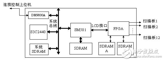
The whole hardware system principle is shown in Figure 1. The S3C2440 and SM501 are connected through the system bus in slave mode, and the SM501 is connected to 8MB of local frame memory. The S3C2440 can directly access the local frame memory of the SM501 through the system bus. The system is connected to the DM9000A 10/100M network chip, and the offline control software of the upper computer is connected to the offline system through the Internet network for real-time control. The offline system implements streaming media functions through the network.
For the digital video output by the SM501, an FPGA is used for acquisition and distribution. The SM501 is connected to the FPGA via an LCD digital interface and contains 24 bit parallel pixel point RGB data, pixel clock pclk, line sync and DE signal. The FPGA collects the pixel data output by the LCD interface and forwards it to the corresponding scanning board of the pixel position in real time. After one frame of image transmission is completed, all the scanning boards will simultaneously update and display the new image frame. Each scanner has a resolution of 256 &TImes; 256, and the offline system can control up to 1024 × 768 resolution. The detailed design of the internal logic of the FPGA is not the main content discussed in this article.

Figure 1 Block diagram of the offline playback system hardware
3 software system
The basic requirements for LED offline playback software design include: the system must be able to run continuously for 7×24 hours, so the playback software must be robust. Although the processing speed of the S3C2440 is relatively fast, the CPU usage of decoding is still a prominent problem. Therefore, the playback software must be efficient, especially to maximize the 2D acceleration display capability provided by the SM501. In addition, because the SoC update speed is very fast, the hardware platform will inevitably have a better choice, so the software must improve its portability under the premise of ensuring high efficiency. Finally, an open software architecture is built that is scalable and scalable to allow for the development of new features.
This article introduces the design of the software part from the following two aspects:
1) Establish an embedded Linux system platform
2) Design and implementation of offline dedicated playback software for LED display
This article will briefly introduce the construction of the embedded Linux system platform based on the S3C2440 platform, and then focus on the design method adopted by the playback software in terms of openness, portability and efficiency.
4.1 Establishing an Embedded Linux System Platform
The Linux kernel has small size, high efficiency, mature and stable, open source code, rich resources, and the kernel directly provides rich network protocols, supporting multiple file systems and many other advantages. This topic transplants the Linux2.6.18 kernel, which has the advantages of good stability and good development tool support. This part of the work mainly includes:
1) Transplant u-boot for hardware platform.
2) Trim and cross-compile the Linux kernel. Porting USB storage disk, DM9000A network chip, SM501 graphics card driver to the kernel
3) Cross-compile busybox to generate Initrd file system image in ext2 format
4) Burn the kernel and Initrd image to Nand Flash via u-boot, set kernel boot parameters and u-boot boot command to start the kernel.
After the above work, a miniaturized embedded Linux platform was established. Due to space limitations, this article does not provide an in-depth introduction to the details of the embedded Linux platform.
4.2 LED display offline dedicated playback software design and implementation
The main design goal of the LED display offline playback software is to support video playback, picture display, multi-region display, streaming media playback, and remote control. Because the whole software project is relatively large, this article will only select a few key modules for detailed description, and focus on how to use the SM501 to achieve high-performance display and video playback. The streaming media playback and remote control sections are not introduced.
4.2.1 Design of multi-zone display function module
As the resolution of LED display screens continues to increase, the demand for information capacity of the same display screen has also increased correspondingly, and this demand is particularly prominent in LED screens for advertising. A typical LED multi-region display scenario is a video region, multiple image regions, and a rolling subtitle region. The offline playback system is mainly for outdoor advertising screens, so it is important to consider the multi-zone display function.
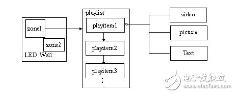
In order to better support the multi-area display of the LED screen, it must be separated from the traditional full-screen display concept to establish a concept based on the zone display, that is, the display content is always displayed on a certain display area, and the single screen display is only A special case of multi-region display. The area on the structure is divided into layers, and the area can be divided into multiple sub-areas. The positions of sibling sub-areas cannot overlap. Thus, in theory, any sub-region display form in units of rectangles can be supported. Multiple regions are displayed in parallel and implemented in a multi-threaded manner.
Each zone contains a playlist. Each playlist consists of a series of display items (playitem). The concept of a display item is a complete display process on a display area. For example, a video is played, a picture is displayed periodically, and the text is displayed. The program adopts an object-oriented design idea to abstract the commonality of different types of display items to facilitate the continuous expansion of new display items and customized display content.
All display items, regardless of their content, can be abstracted into a state machine that changes over time. Each display item completes its own display in the area to which it belongs under the lapse of time, that is, completes a state transition process from initialization to completion. Therefore, playitem is an abstract base class. Each type of display project only needs to reimplement the public call interface provided by playitem.
Each zone has a play thread that continuously fetches a display item from the playlist and performs its state transition interface to complete the display process. This design allows different types of display items to be mixed in the same display list, greatly increasing the flexibility of the playback process arrangement.
The multi-region display design model is shown in Figure 2.

Figure 2 Multi-region display model
aluminium laptop stand amazon,vertical laptop stand india,vertical laptop stand multiple
Shenzhen ChengRong Technology Co.,Ltd. , https://www.laptopstandsupplier.com