An electrolytic capacitor is a type of capacitor. The metal foil is the positive electrode, and the metal oxide film close to the positive electrode is the dielectric. The cathode is composed of conductive materials, electrolyte and other materials. Because the electrolyte is the main part of the cathode, the electrolytic capacitor is named after . At the same time, the positive and negative electrolytic capacitors cannot be connected wrongly. Aluminum electrolytic capacitors can be divided into four categories: lead-type aluminum electrolytic capacitors; bullhorn aluminum electrolytic capacitors; bolt-type aluminum electrolytic capacitors; solid aluminum electrolytic capacitors.
Characteristics of electrolytic capacitors1. The capacitance per unit volume is very large, tens to hundreds of times larger than other types of capacitors.
2. The rated capacity can be very large, and it can easily be tens of thousands of microfarads or even a few farads.
3. The price has an overwhelming advantage over other types, because the constituent materials of electrolytic capacitors are common industrial materials, such as aluminum and so on. The equipment for manufacturing electrolytic capacitors is also common industrial equipment, which can be produced on a large scale with relatively low cost.
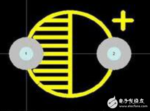
Electrolytic capacitor symbolThis is indicated in the exported PCB. As shown. The plus sign on the right represents the positive side. Of course, some people do not have this plus sign to indicate. The shaded part on the other side represents the negative electrode.
There are many ways to measure electrolytic capacitors, including multimeter detection method, simple fuse detection method, megohmmeter detection method, capacitor capacitance measurement, incandescent bulb and capacitor series detection method, etc. The following describes how these methods are measured.
1. Multimeter detection method. For fixed capacitors above 0.01 microfarad. The resistance 1K block of the multimeter can be used to directly test whether the capacitor has the charging process and whether there is internal short circuit or leakage, and the capacity of the capacitor can be estimated according to the amplitude of the pointer swing to the right. During the test operation, first touch the two pins of the capacitor at will with two test leads, then change the test leads and touch again. If the capacitor is good, the pointer of the multimeter will swing to the right and then quickly return to the infinity position to the left. The greater the capacitance, the greater the amplitude of the pointer swing. If the meter pen is repeatedly exchanged and touches the two pins of the capacitor, the pointer of the multimeter never swings to the right, indicating that the capacity of the capacitor has been lower than 0.01 microfarad or has disappeared. During the measurement, if the pointer cannot return to the infinity position to the left after swinging to the right, it indicates that the capacitor has leaked or has been broken down.
2. Simple fuse detection method. Use a fuse and the capacitor to be tested to be connected in series to a 220 volt AC power supply. If the fuse of the fuse blows, it means that the capacitor has been short-circuited. If the fuse of the fuse does not blow, after a few seconds of charging, cut off the power supply, and use a screwdriver with an insulated handle to short-circuit the two poles of the capacitor to discharge. Sparks occur, indicating that the capacitor is good. On the contrary, it means that the capacitance of the capacitor has become smaller or has been opened. Use this method to judge the quality of the capacitor should be repeated several times to get the correct conclusion.
3. The megohmmeter detection method. A megohmmeter can also be used for testing. Shake the handle, if the pointer is at infinity, it means that the capacitor is open; if the pointer is at zero, it means that the capacitor is short-circuited. The ground test of the capacitor can also be done by connecting the terminals of the megohmmeter to the terminals and the shell of the capacitor respectively. Shake the handle, if the pointer is at zero, it means that the capacitor is connected to ground.
4. Measurement of capacitance of capacitor. In the absence of special meters, a multimeter can be used to measure the capacitance of a power capacitor. The specific method is: use a fuse and a capacitor to be tested in series to connect to a 220 volt AC power supply. Use the AC voltage file of a multimeter to measure the voltage across the capacitor. Then get the capacitance of the capacitor through the calculation formula.
5. Incandescent bulb and capacitor series detection method. Connect the incandescent bulb and the capacitor in series to the 220V AC power supply. If the brightness of the incandescent bulb is darker than connecting it directly to the 220V AC power supply, the capacitor is good; if the incandescent bulb is not bright, it indicates the capacitor to be tested. If the brightness of the incandescent bulb is the same as the brightness when it is directly connected to the 220V AC power supply, it means that the capacitor's interior has been short-circuited.
How to judge the positive and negative electrodes of electrolytic capacitorAppearance discrimination. First take out an electrolytic capacitor. The first method is to look at the electrolytic capacitor hose, which has a negative sign printed on one end of the hose. The positive pole at the other end is not indicated. The second method is to look at the electrolytic capacitor pin. One end of the pin with a grid represents the negative electrode, and the other end represents the positive electrode.
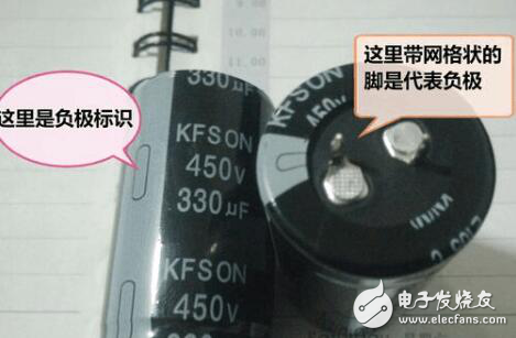
Let’s look at the electrolytic capacitor of this plug-in. The pin has one long and one short. The long one is the positive pole and the short one is the negative pole. If you can’t judge the length of the pins, you can also see from the electrolytic capacitor hose that there is a screen-printed negative logo on one end. In addition to the screen-printed negative logo, there is also an introduction to the basic parameters of the electrolytic capacitor.
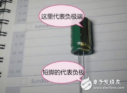
There is another kind of electrolytic capacitor that is not like this, but a lead-pin type. See the lower right picture: This kind of capacitor first looks at the guide pin, and the long end of the guide pin is the positive pole. The short end of the lead pin is the negative pole. At this time, if someone asks me, how to judge the positive and negative poles of some electrolytic capacitors that have been cut corners? At this time, you will find that the short end of the electrolytic capacitor hose guide needle will have a label of the negative electrode of the electrolytic capacitor.
In addition to appearance identification, it can also be measured by an instrument. Find a desktop power supply, reduce the voltage, connect your electrolytic capacitor to the output end of the power supply, and then turn the capacitor upside down, and observe the change of the ammeter. When the current is large, it is proved that the positive and negative poles of the capacitor are just the same. The positive and negative power is reversed, so that the capacitor will not be damaged. If there is no such power supply, you can find a low voltage. The electrolytic capacitor will generate heat if it is connected reversely. Of course, if the voltage is too low, there will be no response. This method will damage the capacitor. If the connection is reversed and the voltage is too high, the inside of the electrolytic capacitor will be damaged, and the poor quality will even explode, so this measurement is too recommended for novices.
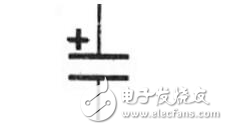
as the picture shows. The following is the identification of the circuit diagram of the positive and negative electrodes of the electrolytic capacitor. Electrolytic capacitors are identified by the letter C in the circuit.
Marine baffle control box,baffle control box,Marine baffle controller,baffle controller
Taizhou Jiabo Instrument Technology Co., Ltd. , https://www.taizhoujiabo.com