Serial communication is a way of data transmission. This method is simple in operation, has few connections, and has a long transmission distance, and thus has been widely used in information transmission, especially in long-distance transmission. Currently commonly used serial communication methods are RS-232 C, RS-422 A, RS-423 A and RS-485 A. RS-232 C is a universal serial interface that transmits signals in levels. It can exchange information between two devices with only 3 wires. The maximum transfer rate is 20 Kb/s, which allows the most between devices. The distance is 15 m. In order to improve the low transmission rate of RS-232C and the short transmission distance, EIA has introduced RS-422 A, RS-423 A. RS-485 A, etc. The RS-422 A transmits signals in differential form. Each channel uses two signal lines. Only one transmitter is specified in the circuit. The maximum transmission rate is 10 Mb/s, and the farthest transmission distance at this rate is 120 m. If the baud rate is reduced to 90 Kb/s, the communication distance can be extended to 1200 m. The RS-423A transmits signals in an unbalanced differential form. RS-485A allows the presence of multiple transmitters. They all have some common characteristics, that is, the transmission rate is low, the transmission rate and the transmission distance affect each other, and the transmission medium is required to be high, and a shielded cable is generally required. When the transmission distance is long or there are many connected devices, the cost of the system is increased.
With the continuous development of computer applications, in some occasions, high-speed, long-distance transmission of signals is required, while at the same time minimizing costs. To meet this requirement, this section takes serial communication between microcontrollers as an example to introduce a serial communication device that can achieve high speed and long distance.
First, the characteristics of the single-chip serial portAt present, most single-chip microcomputers are equipped with serial interfaces. For example, 51 single-chip microcomputers and MCS-96 series single-chip microcomputers are equipped with a full-duplex serial interface, which can receive and transmit signals at the same time. Taking 51 single-chip serial port as an example, there are 4 serial working modes. The baud rate can be set by software and generated by the on-chip timer. Both receiving and transmitting can work in interrupt or query mode, which is more flexible. The interface typically operates in an RS-232C or RS-422A mode via an interface circuit, so it has the characteristics of RS-232C or RS-422A. The four working methods are as follows.
1. Mode O
Synchronous shift register mode with a baud rate of fosc/12. Fsc is the oscillation frequency of the oscillator, the data is input by the RxD terminal, the synchronous shift pulse is output by the TxD terminal, and the transmission/reception is 8-bit data. This method is generally used to extend the parallel interface, keyboard or display interface.
2. Mode 1
Serial operation mode, RxD reception, TxD transmission, each frame of information is 10 bits, including 1 start bit, 8 data bits and 1 stop bit. The baud rate of receiving/transmitting is:
In the formula: SMOD=1 or 0, set by software; N is the timer self-loading constant set by software, its value is 0~255. When SMOD-1. When N-255, the baud rate is the highest, which is fosc/192. When SMOD=0, N=O, the baud rate is the lowest, which is:
3. Mode 2
Serial operation mode, 11-bit data per frame, including 1 start bit, 8 data bits, 1 programmable bit, 1 stop bit. The programmable bit should be set to O or 1 as required. The baud rate of its receiving/transmitting is:
When SMOD=1, the maximum baud rate is fosc/32; when SMOD-0, the minimum baud rate is fosc/64.
4. Mode 3
Serial communication mode, the transmission format is the same as mode 2, and the baud rate is the same as mode 1. That is, the maximum baud rate that can be obtained in this way is fosc/192, and the minimum baud rate is ose/98 304.
Comparing the three serial working modes, the mode 2 has the highest baud rate. For the 51 MCU, when fosc=12 MHz (the highest crystal oscillator of 51 MCU), it is available.
These values ​​are much higher than the baud rate of the commonly used serial port. Therefore, when serial communication is between the MCU (51 MCU, etc.), in the case of crystal oscillator selection, only mode 2 can be selected to obtain the highest baud rate. . In order to receive/transmit signals over long distances, certain measures must be taken on the circuit. To this end, introduce a circuit that can receive/transmit signals over long distances.
Second, the composition of the block diagram1. Signal representation
(1) representation of 1
When the TxD output is 1, after the receiving/transmitting circuit, a high-resistance signal appears on the bus, and the receiver changes the high-impedance signal to 1 through the receiving/transmitting circuit to send the RxD. When the serial port is not working, TxD is 1, and the corresponding bus is high impedance.
(2) representation of 0
A rectangular wave of one period is used to represent 0, and the period of the rectangular wave is 32 or 64 times of the oscillation period. When TxD outputs 0, a rectangular wave of one cycle appears on the serial bus after passing through the transmit/transmit circuit. After the signal is converted by the receiver transceiver circuit, it becomes 0 again at the RxD terminal.
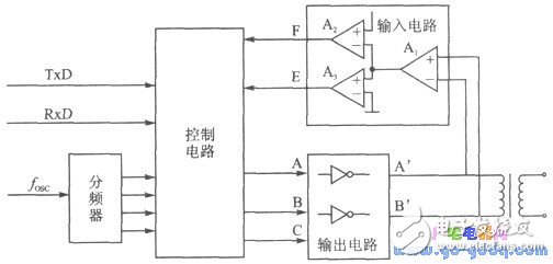
2. Block diagram of the receiving/transmitting circuit
The block diagram of the receiving/transmitting circuit is shown in Figure 1-17. The device is composed of a control circuit, a frequency divider, an output drive, a differential input, a coupling transformer and the like. The control circuit consists of a GAL circuit or a gate circuit. The output drive uses a three-state gate. The differential input uses three op amps to form a two-stage comparison circuit. The frequency divider provides the reference and state change conditions for the control circuit operation. Used to implement the input or output of a signal.
Thermal Overload Relays are protective devices used for overload protection of electric motors or other electrical equipment and electrical circuits,It consists of heating elements, bimetals,contacts and a set of transmission and adjustment mechanisms.
Our Thermal Overload Relays had been divided into five series(as follow),with good quality and most competitive price,had exported into global market for many years:
LR1-D New Thermal Relay
LR2-D Thermal Relay
LR-D New Thermal Relay
LR9-F Thermal Relay
Intermediate Relay
The working principle of the thermal relay is that the current flowing into the heating element generates heat, and the bimetal having different expansion coefficients is deformed. When the deformation reaches a certain distance, the link is pushed to break the control circuit, thereby making the contactor Loss of power, the main circuit is disconnected, to achieve overload protection of the motor.
As an overload protection component of the motor, the thermal relay has been widely used in production due to its small size, simple structure and low cost.
111")
Thermal Overload Relay,Telemecanique Overload Relay,Thermal Digital Overload Relay,Telemecanique Model Thermal Relay
Ningbo Bond Industrial Electric Co., Ltd. , https://www.bondelectro.com