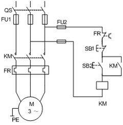
Circuit controlled by a knife switch as a main protection

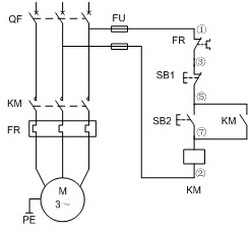
Circuit protected by air switch as main circuit
Working process: press the control start button SB2, the contactor KM coil is energized by the iron core, the main contact is closed to make the motor run electrically, and the auxiliary normally open contact is also closed at the same time to realize the self-locking of the circuit, and the power supply passes through FU1→ SB1 normally closed → KM normally open contact → contactor coil → FU2, release SB2, KM will not be powered off. When the stop button SB1 is pressed, the SB1 normally closed contact opens, the KM coil is de-energized, the main and auxiliary contacts are opened, and the motor is de-energized to stop operation. FR is a thermal relay. When the motor is overloaded or the motor current increases due to the fault, the bimetal in the thermal relay will rise in temperature and the FR normally closed contact will open. The KM will be de-energized and the motor will be de-energized to stop operation. .
Explain the function of each component and select various electrical appliances according to the given motor capacity.
Rated current of the switch (QS or QF):
(1) The knife switch functions to turn the power on and off, and can be selected by 3 times the rated current of the motor.
(2) The air switch is divided into a power supply and has the function of short circuit protection, which can be selected equal to or slightly larger than the rated current of the motor.
The fuse (FU) acts as a short circuit protection:
It can be selected within the rated current range of the motor (1.5~2.5).
The AC contactor (KM) turns the motor on and off and has the function of voltage loss protection:
The rated current of the contactor can be selected within the range of (1.3~2) motor rated current.
Overcurrent protection components for thermal relay (FR) motors:
The rated current In of the thermal element. It can be selected within the range of (1~1.5) motor rated current In; the rated current of the thermal relay should not be less than the rated current of the thermal element.
Its protection setting value IFR = motor rated current In.
Thermal relay adjustment:
There are two types of automatic reset and manual reset (automatic reset mode is set at the factory). If you need to use manual reset, you can use a small screwdriver to extend into the adjustment hole, and turn the three buttons counterclockwise.
After the thermal relay is overloaded, it can be reset within 5 minutes in the automatic reset mode; in the manual reset mode, press the reset button to reset after two minutes.
Can the thermal relay in the device control circuit change the reset mode at will? why?
The thermal relay in the device control circuit can not change the reset mode arbitrarily. At this time, when the thermal relay is activated, the requirements for restarting the device are different. If the manual reset is changed to automatic reset, it may cause the device. Startup error.
Main circuit lead: Select according to the wire selection port.
Control loop wire: Use insulated copper wire of not less than 1.5mm2.
Control loop fuse (FU2): 5A or 10A fuses can be used with 1.5A fuses.
The wire and the actual wiring (actually) are protected by the air switch in the main circuit
Example: Wiring a 7.5kw motor in one direction, using various electrical components and wires
1. The rated current of the 7.5kw motor is 15A.
2. Switch: HQ-60/3 rubber cover brake or HK-60/3 iron shell switch can be used.
3, the main circuit fuse: optional RClA-30/30 ceramic plug-in fuse, or RL1-60/30 spiral fuse.
4. AC contactor: Any one of B25, CJ20-25 and CJ10-20 can be used.
5, thermal relay: JR16-26/3D can be selected, the rated current of the thermal component is 22A or 16A, and it is set at 15A.
6. Control loop fuse: RClA-5/3 or RL1-15/2 can be used.
4 Bay Fm Dipole Antenna,Fm Broadcast Dipole Antenna,Four-Bay Fm Dipole Antenna,4 Wave Dipole Antenna
Anshan Yuexing Technology Electronics Co., LTD , https://www.yxhtfmtv.com