For large machines like gantry milling machines, it is necessary to use two motors to simultaneously push the beam or the table. Therefore, the two motors are required to work in full synchronization. In the numerical control system, this function is called "servo synchronization". The Mitsubishi CNC system has this function. The author recently used the Mitsubishi M64S system + MDS-RV type driver to be equipped with a medium-sized gantry milling of a customer. The "servo synchronization" function is used to form a semi-closed loop system, which achieves good processing results.
1. Implementation of servo synchronization function

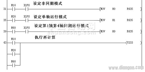
Figure 1. Programming the plc program for servo synchronization
To implement the servo synchronization function, the relevant program must be programmed on the PLC ladder diagram:
In the Mitsubishi M64CNC interface, R435 is a data register that determines the servo synchronization function. Set different values ​​for R435, you can specify any two axes to enter the "servo synchronization" mode. The first axis and the fourth axis are specified in this article. The first axis is the reference axis (X) and the fourth axis is the driven axis (A).
The correction mode is often used in the early stages of debugging. For the semi-closed loop system, when the mechanical precision affects the imbalance of the two axes, it will cause the "synchronous error too large" alarm. At this time, it is necessary to enter the "correction mode" and adjust one of the axes. In the "correction mode", you can only operate with "handwheel mode". The interface for the correction mode is - Y22A.

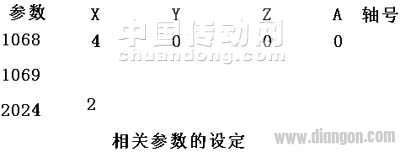
figure 2
2. Related parameters
Parameter #1068————————- This parameter specifies the "axis number of the slave axis". (must be set under the reference axis name)
Parameter #2024——————————Set the synchronous error value (only set under the reference axis name)

image 3
3. Origin setting
For the two servo axes of the servo synchronization, the origin setting is whether the two axes respectively set the origin or only one origin? In theory, of course, each axis should be set to the origin. However, from the practical point of view, the two servo motors are installed at the ends of the beam of the gantry milling machine. During the operation, due to the influence of mechanical precision error, when the actual running distance of a certain 1 axis is ahead or 2 mm behind the other axis, it will cause One of the alarms (current is too large).
If each axis is set to the origin, it will bring great difficulty to the installation of the two origin switches. Moreover, for gantry milling, the two servo axes move forward and backward at the same time, wherein one axis reaches the machine origin position, and the other axis reaches the position as the origin position. If the stroke error of the two axes exceeds a certain value, an "(current too large)" alarm will be generated. Therefore, there is no problem of "false return to origin" of a certain axis.
Therefore, during the actual debugging process, only one origin signal is set for the two servo synchronous axes, and the origin signal is set on the side of the reference axis.
4. Problems encountered during homing
Even if only one origin is set, the following occurs when performing the homing operation: When the reference axis returns to the origin, the slave axis repeatedly appears "(current too large)" alarm. Unable to complete the operation of both axes returning to the origin at the same time. Of course, you can't enter the automatic state.
After the servo synchronization function is activated, during the jog operation and the handwheel operation, due to the mechanical installation and the accuracy of the lead screw, each time only 30-50mm is run, the "(current too large)" alarm will appear. The solution to the on-site commissioning is to increase the parameter #2213 (current limit value) (the maximum value is 500% of the static rated current). However, if the parameter is too large. It is possible to damage the mechanical system, especially for newly assembled machines, the #2213 parameter should be carefully adjusted. The fundamental solution is to perform mechanical accuracy error compensation immediately after the homing operation is completed. The electrical accuracy is consistent with the actual accuracy.
However, now I have encountered problems even back to the origin..........
Careful observation on the display, the alarm phenomenon of the process of returning to the origin occurs in this way: when the reference axis (X) returns to the origin, the slave axis (A) continues to run 1.6-1.8mm and an alarm occurs. This means that the difference between the electrical origins of the two axes is at least 2-3 mm.
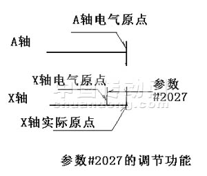
After carefully analyzing the parameters of the homing point, you can see parameter #2028 (grid cover amount), #2027 (origin offset) is the most critical. Where parameter #2027 (origin offset) refers to the "distance between the electrical origin and the actual origin". There is now a deviation in the origin between the two axes. By adjusting parameter #2027, you can make it consistent. The unit of parameter #2027 is 1/1000mm. Set #2027=3000 of the reference axis (x), and then return to the origin operation, and the two axes are simultaneously returned to the origin. Prove that the above analysis is correct.

Figure 4
In order to make the origin of the two axes reach a relative consistency. Using the "servo monitor" screen on the display, the current value of the reference axis (x) is monitored, and parameter #2027 is repeatedly adjusted. When the current value of the reference axis (x) is <20%, it can be considered that the basic requirement is met.
5. Compensation for mechanical precision error
For the servo-synchronized dual-drive system, the "mechanical accuracy error compensation" must be performed immediately after the completion of the homing operation. Obviously, if the "mechanical accuracy error compensation" is not made, the "current" will often be caused due to mechanical errors. Too big "alarm. This can be considered as an initial compensation. After the break-in, it should be compensated once more.
6. Problems caused by soft limits
Another problem encountered during the operation of the servo synchronous dual drive system is that when one of the axes runs to the soft limit, one axis stops and the other axis continues to run, and an "current too large" alarm is generated. (Although the soft limit values ​​set by the two axes are the same.). This situation is obviously caused by the cumulative error of mechanical precision. Once an alarm is generated, the alarm axis must be adjusted in handwheel mode. This is very troublesome for the operator. How to avoid this situation?
One way is to install a hard switch, use this signal to cut off automatic and manual operation. But this will increase the point of failure.
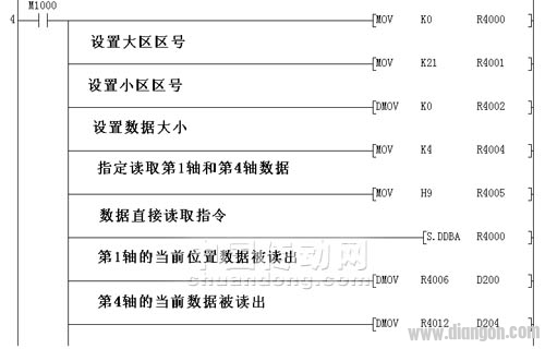
Another way is to use the DDB function to take a point before the soft limit, use this signal to cut off automatic and manual operation. This method does not increase the cost and point of failure. Methods as below:

Figure 5. Implementation of the DDB function
Compare the read current position data of the 1st and 4th axes (D200/D204) with a fixed point before the soft limit. When the current position of the 1st and 4th axes exceeds the fixed point position, the automatic and manual operation is cut off. Avoid the mechanical encounter with soft limits. Equivalent to adding another protection.
After the above processing, the two synchronous axes can be stopped normally. No alarms appear.
This is also an effective way to solve the mechanical accumulation error.
Transparent Led Film Screen,Adhesive Transparent Led Display,Adhesive Led Transparent Film Screen,Transparent Led Display Film Screen
Guangdong Rayee Optoelectronic Technology Co.,Ltd. , https://www.rayeeled.com