The Zero Intermediate Frequency (ZIF) architecture has emerged since the early days of the radio. Today, the ZIF architecture can be found in almost any consumer radio application, whether it's a TV, a mobile phone, or a Bluetooth technology. The reason for this widespread popularity is mainly because experience has repeatedly proven that in any radio technology, the architecture has the lowest cost, lowest power consumption and smallest size. Historically, this architecture has been used sparingly in applications that require high performance. However, as wireless connectivity demands continue to grow and spectrum becomes increasingly crowded, there is a need to change the status quo to continue to deploy radio technology economically in the infrastructure to support our wireless needs. Contemporary zero-IF architectures can meet these needs because the many common pitfalls of these architectures have been overcome by a combination of process, design, partitioning, and algorithms. The latest advances in ZIF technology have created challenges for existing high-performance radio architectures, and new products have achieved breakthroughs in performance, enabling new applications that were previously unmatched by ZIF technology. This article explores the many advantages of the ZIF architecture and introduces these advantages to new heights in radio design performance.
Challenges for radio engineersThe ever-increasing demand poses challenges for today's transceiver architects as our demand for wireless devices and applications continues to grow. As a result, consumers need to continue to access more bandwidth.
For several years, designers have moved from single-carrier radios to multi-carrier radio technologies. When the spectrum of a frequency band is fully occupied, a new frequency band is allocated; currently, more than 40 wireless frequency bands must be served. Since operators have spectrum in multiple frequency bands and these resources must be coordinated, today's trend is toward carrier aggregation, which in turn leads to multi-band radios. This in turn leads to more radios with higher performance, better out-of-band rejection, better radiation performance, and lower power consumption levels.
Although wireless demand is growing rapidly, power consumption and space budgets have not increased. In fact, it is important to reduce both carbon emissions and physical size while increasing power and space savings requirements. In order to achieve these goals, we need to understand the radio architecture and partition from a new perspective.
integratedIn order to increase the number of radios in a particular design, the size of each piece of radio must be reduced. The traditional approach is to gradually integrate more designs into a single piece of silicon. While this may be sensible from a numerical perspective, integrating analog functionality for integration does not make sense. One of the reasons is that many of the analog functions in the radio cannot be effectively integrated. For example, in the conventional IF sampling receiver shown in Figure 1, the IF sampling architecture has four basic stages: a low noise gain and radio frequency selection stage, a frequency conversion stage, an intermediate frequency gain and selection stage, and a detection stage. The selection stage generally uses SAW filters. These devices cannot be integrated, so they must be deployed off-chip. Although the RF selection stage is provided by piezoelectric or mechanical devices, sometimes the IF filter uses an LC filter. Although LC filters can sometimes be integrated into a monolithic structure, the sacrifice of filter performance (Q and insertion loss) and the necessary increase in the digitizer (detector) sampling rate increase the total power consumption.
Digitizers (analog-to-digital converters) must be fabricated in a low-cost CMOS process to keep cost and power consumption at a reasonable level. Of course, it can be fabricated in a bipolar process, but the result is an increase in device size and power consumption, which is contrary to the original intention of optimizing the size. Therefore, the standard CMOS process is the best manufacturing process for this function. This poses a significant challenge for integrating high performance amplifiers, especially at the mid-range. Although CMOS processes can integrate amplifiers, it is difficult to achieve the required performance from processes optimized for low power and low voltage. In addition, the on-chip integrated mixer and IF amplifier require interstage signals to be routed off-chip to access the IF and anti-aliasing filters, which are then digitized, thus losing the benefits of integration. This will not achieve the purpose of integration, as the result will increase the number of pins and package size. In addition, critical analog signals sacrifice performance each time they pass a package pin.

Figure 1. Traditional IF Sampling Receiver
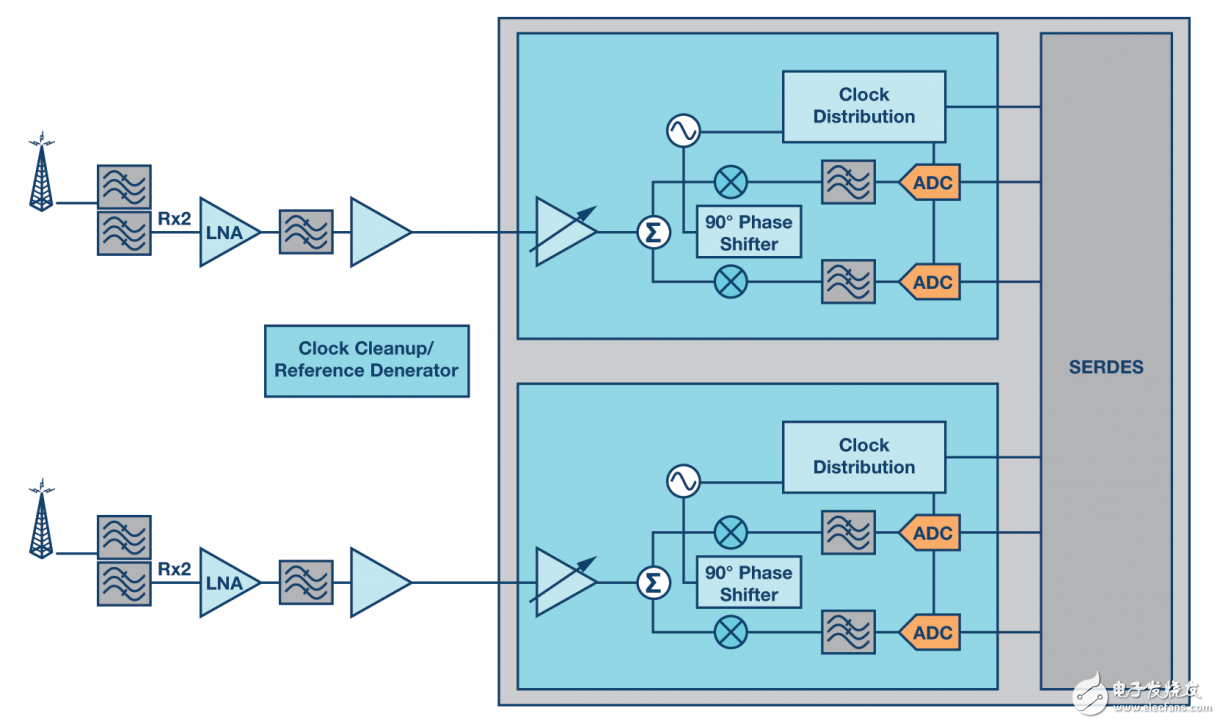
The best way to integrate is to partition the system and eliminate components that cannot be integrated. Since SAW and LC filters cannot be effectively integrated, the best option is to determine how to eliminate them by redesigning the architecture. Figure 2 shows a typical zero-IF signal chain that converts the RF signal directly into a composite baseband, completely eliminating the need for an IF filter and an IF amplifier, and achieves these goals. The selection stage is implemented by introducing a pair of low-pass filters in the I/Q baseband signal chain, which can be integrated as an active low-pass filter rather than a higher-power off-chip fixed-IF device. Traditional IF SAW filters or LC filters are inherently fixed devices, and these active filters can be tuned electronically from hundreds of kHz to hundreds of mHz. Changing the baseband bandwidth allows the same device to cover a wider bandwidth without changing the bill of materials or switching back and forth between different fixed IF filters.

Figure 2. Typical zero IF sampling receiver
Grinch T Shirt,Sweat T Shirt,White Long Sleeve,Custom T Shirt Design
GUANGZHOU LIWEI ELECTRONICS CO.,LTD , https://www.gdliwei.com