Figure 1 shows the relationship between the forward current and the forward voltage of six randomly selected white LEDs (three of which are from two top manufacturers). In this case, if you use 3.4V to drive these six LEDs , The corresponding forward current varies greatly: 10mA to 44mA.
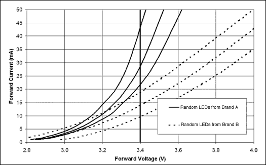
Figure 1. Six randomly selected white LEDs (three of which are from two top manufacturers) corresponding curve of forward current and forward voltage. Note that for any given voltage, the range of forward current varies from -10mA to 44mA (at 3.4V).
In order to ensure reliability, the current driving the LED must be lower than the LED rated value. The typical maximum value is generally 30mA. However, as can be seen from Figure 2: When the ambient temperature increases, the allowed rated current will decrease. When the temperature reaches 50 ° C, the current needs to be limited to 20mA. It is not difficult to draw such a conclusion by observing Figures 1 and 2: the scheme of driving the white LED with the constant voltage method is less reliable.
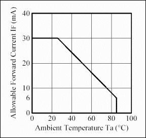
Figure 2. In general, the maximum absolute value of white LED forward current decreases with increasing ambient temperature (Courtesy Nichia CorporaTIon).
In addition, driving a white LED with a constant current can also achieve consistency in brightness and chromaticity. Figure 3 shows several common white LED driver circuits.
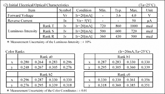
Figure 3. For a typical white LED, the electrical characteristics are usually tested at IF = 20mA. Therefore, in order to obtain the predicted and matched brightness and chromaticity, it is recommended to use a constant current drive (Courtesy Nichia CorporaTIon).
Figure 4 shows four commonly used power circuits for driving LEDs. Fig. 5 is the corresponding current adjustment accuracy obtained by adjusting the above 6 LEDs. The output load line of the regulator in Figure 5 is drawn on the Vf curve of the LED. The intersection of the two curves is the adjustment point of each LED.
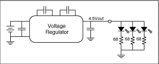
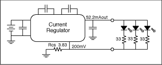
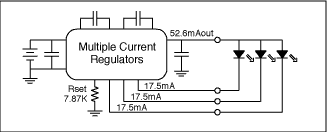
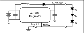
Figure 4. White LEDs usually have four different drive circuits: (a) voltage source and ballast resistance, (b) current source and ballast resistance, (c) multiple current sources, (d) one current source drive in series LED.
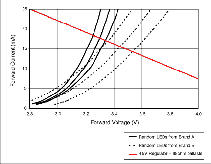

Figure 5. The forward voltage (Vf) of each white LED has different effects on the regulation current accuracy, depending on the structure of the regulation circuit: (a) voltage source and ballast resistance, (b) current source and ballast resistance, (c ) Multiple current sources or one current source drive series LEDs. The Vf curve of 6 LEDs (three from manufacturer A and manufacturer B) is shown in the figure. The intersection of the output load curve of the regulator and the LED Vf curve is the stable adjustment operating point.
The circuit shown in Figure 4a uses a voltage stabilizing source and a ballast resistor to control the LED current. The advantage of this structure is that there is a lot of room for selecting a voltage source. Only one connection endpoint is required between the regulator and the LED; This is mainly caused by the loss of ballast resistance. In addition, it does not control the LED forward current very accurately. From the test curve in Figure 5a, it can be seen that the current variation range of six different LEDs is: 14.2mA to 18.4mA. The average brightness of LED provided by manufacturer A is higher than that of manufacturer B, and the operating current is 2mA higher.
The circuit shown in Figure 4b is used to adjust the total current of the LEDs, and the ballast resistance is used to achieve matching between the LEDs. This structure is used in the MAX1910. This circuit can achieve better results when driving the same batch of products from the same manufacturer. Under the condition of providing the same current as the above circuit, the ballast resistance can be reduced and the power consumption can be reduced by half. Figure 5b shows the variation range of six different LED drive currents: 15.4mA to 19.6mA. The LED current provided by manufacturer A has a smaller change. The average control current of LEDs from manufacturer A and manufacturer B is the same: 17.5mA. The disadvantage of this structure is that the power consumption of the ballast resistor is still large, and the current matching of each LED is not very good. However, this circuit compromise takes into account performance and circuit simplicity.
Figure 4c can adjust the current of each LED separately, without ballast resistance. The current regulation accuracy and matching degree depend on each independent current regulator. The MAX1570 uses this current source structure, with a current accuracy of 2% and a matching degree of 0.3%. Since the current regulator allows a lower voltage drop, higher efficiency can be obtained. Figure 5c shows that the current of all six white LEDs tested is maintained at a stable 17.5mA. Since the ballast resistance is omitted, the circuit board area can be effectively saved, but four connection terminals are required between the regulator and the LED. This kind of circuit can provide higher performance index and is based on the competitive scheme of inductance structure.
Fig. 4d is an inductance-based booster circuit, which is configured as a current regulator with higher conversion efficiency. The lower feedback threshold further reduces the power consumption of the current-sense resistor. In addition, because the LEDs are connected in series, the brightness of the LEDs can be kept consistent under any operating conditions. The current accuracy depends on the accuracy of the feedback threshold of the regulator and is not affected by the change in the LED forward voltage. The MAX1848 and MAX1561 are two typical examples of such current regulation circuits. The conversion efficiency (PLED / PIN) can reach 87% (3 LEDs in series) or 84% (6 LEDs in series). Another advantage of this circuit is that only two connection endpoints are required between the regulator and the LED, which provides a certain flexibility for the user's design. However, due to the use of inductance in the circuit, compared with the above scheme, the size is larger, the cost is higher, and the EMI radiation is also larger.
Decorative Outdoor Curtain Led Display Screen is the perfect architectural decoration patterns in the daytime and night. And it becomes LED Display screen to display image and video at night.It is ultra light weight design, which is easy to install. The convenient installation help everyone can install it easily by oneself. It can be packaged in one CMB which is save a lot in transportation. It is not only good for transport but also good for maintenance. Front and back maintain are available due to its special design.LED curtain mesh screen can be installed directly on the wall or glass. The hollow design makes permeability up to 70% which is conducive to ventilation and lighting. The exquisite appearance is good for decoration of shopping mall, hotel, office building and 5s shop etc.The frame shell save install material can be fixed easily. High-intensity sealed lamp with high quality up to IP67 protection level. The beautiful patterns can be customized for customer.LED curtain mesh screen can display text, image and video. Low power consumption is also good for long life span.IP67 protection rate features waterproof, anti-dust, wind resistant and anti-corrosion which is suitable for all kinds of using environment.LED curtain mesh screen is very easy to set up. The cabinet was designed by our engineer very attentively and adopted advanced technology to manufacture which support front and rear installation. Cooling with wind is environment friendly and make noise free.Led Curtain Screen is widely used in stadium, shopping mall, 5s car shop and theme park etc.
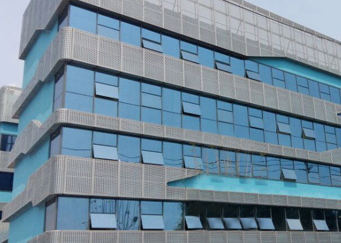
Outdoor Curtain Led Display,Curtain Led Screen,Led Curtain Screen,Outdoor Led Curtain
Shenzhen Bako Vision Technology Co., Ltd. , http://www.rentalleddisplays.com