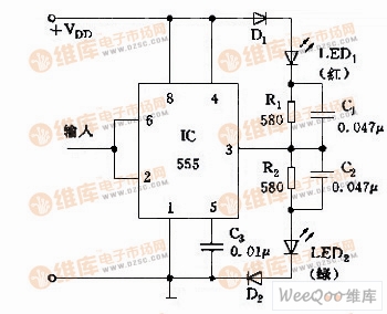
Using the trigger end (2 feet) of the 555 circuit and the set and reset characteristics of the threshold end, a test pen can be formed to detect whether the state of the digital logic is normal, as shown in the figure.
When the probe input is low level “0â€, LED2 (green) is on; when the high level “1†is input, LED1 (red) is on. The R1C1 and R2C2 networks are acceleration networks.
The logic pen is suitable for testing digital circuits such as TTL and MOS, and VDD is optional within 5 to 15V.

555 digital logic test pen circuit
The antenna assembly harness are passed heat and other kinds of tested.
This is auto cable .OEM/ODM specification for you.welcome to your inquiring with drawing pictures or sample.
If sample offered by clients ,according machines inspection, datas of this kind of cable will be know by our technician .
If only drawing pictures ,please offer the 3D drowing pictures.
Custom Wiring Harness,Copper Material Wire Harness,Board Connector Terminal Wire Harness,Antenna Assembly Harness
Dongguan YAC Electric Co,. LTD. , https://www.yacentercn.com