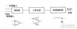
The power amplification (referred to as power amplifier) ​​circuit in the general audio-visual circuit is to further amplify the low-frequency signal after the voltage amplifier to obtain a larger output power, which is ultimately used to push the speaker to play or provide deflection current in the TV.
1. Characteristics of power amplification current
The understanding or evaluation of the power amplifier circuit is mainly considered from the three aspects of output power, efficiency and distortion.
1. In order to obtain the required output power, the circuit must select a triode with sufficient collector power consumption, and the working current and collector voltage of the power amplifier tube are also high. In the circuit design and use, we must first consider how to fully play the function of the transistor without damaging the transistor. Because the working state of the power amplifier tube in the circuit is often close to the limit value, be careful when adjusting and using the power amplifier current, and should not be used beyond the limit.
2. In terms of energy consumption, the power output by the power amplifier is ultimately provided by the power supply. For example, the power consumption of the power amplifier in the radio should account for 2/3 of the whole machine. ratio.
3. The input signal of the power amplifier circuit has been amplified by several stages and has sufficient strength, which will cause the working point of the power amplifier tube to move greatly, so the power amplifier circuit is required to have a larger dynamic range. If the working point of the power amplifier tube is not selected properly, the output will be seriously distorted.
Second, the principle of commonly used power amplifier circuit
The output of the power amplifier circuit with a single transistor output is small and low in efficiency, which is rare in household appliances. At present, the form of push-pull circuit is often used.
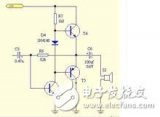
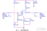
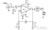
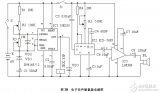
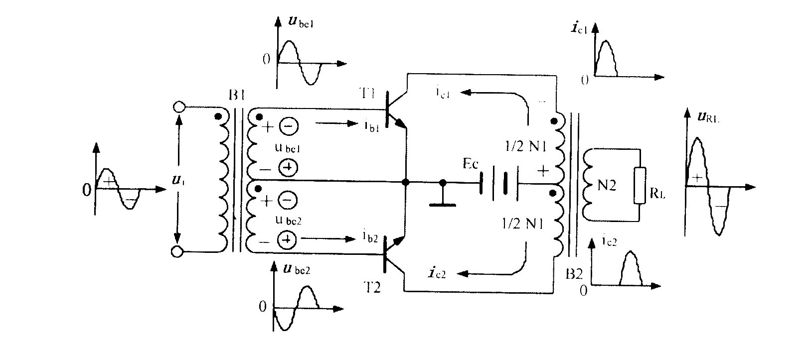
Figure 1 is a schematic diagram of a push-pull circuit using a coupling transformer. Its characteristic is that the triode's static working current is close to zero, and the amplifier consumes less power. When there is a letter input, although the working current of the circuit is large, most of the power is output to the load, but the loss itself is not large, so the power supply utilization rate is high. In this circuit, each transistor only works within half a period of the signal. In order to avoid distortion, two transistors are used to work in coordination. The secondary of the input transformer B1 in the figure has a grounded center tap. When the audio signal is input, two equal-sized and opposite-polarity signals of B1 secondary are sent to the transmitting junctions of BG1 and BG2, respectively. During the positive half cycle of the input signal, the BG1 tube is cut off due to the application of reverse bias. Only BG2 can amplify the signal and output it from the collector; while in the negative half of the signal, BG1 gets a positive high bias, which The signal of the period is amplified and output, but BG2 is cut off. Although the two transistors in the circuit each amplify the signal for half of the same period, their output currents are passed through the output transformer B2, so the induced current obtained at the secondary of B2 can all become a complete output signal.
 |
In this power amplifier circuit, in order to solve the problems of impedance turns and signal phase, the input and output transformers are indispensable. However, the production of high-quality transformers is difficult in terms of materials and processes. It always consumes a part of energy itself, reducing the efficiency of the circuit, and the frequency characteristics of the transformer are not good, making the circuit very uneven to the signal output of different frequencies, which will cause Distortion, so in order to improve the quality of the power amplifier, people use transformerless (OTL) power amplifier circuits more.
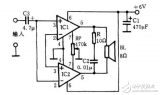
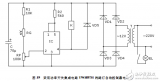
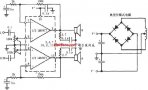
Figure 2 is a schematic diagram of a complementary symmetric push-pull power amplifier circuit. Two transistors with the same amplification performance and opposite conductive polarities (called complementary tubes) are used here. In the picture, BG1 is an NPN tube. During the positive half of the input AC signal of the amplifier, for the BG1 tube, the base voltage is positive, the emitter is negative, and the emitter junction is forward biased. The triode can work. But BG2 is terminated due to the reverse bias applied to the launch junction. Therefore, the positive half of the signal is amplified by the BG1 tube. In the negative half cycle of the signal, the situation is reversed. The BG2 tube can work to amplify the negative half cycle of the signal. The amplified signal is sent by two transistors in turn, and the complete signal is synthesized again on the speaker.
 |
The two transistors in the push-pull circuit each amplify the signal for a half period, which requires that the amplification performance of the two transistors are similar (with a β value within 10% of the difference), otherwise the amplified signal will have different amplitudes in the two half periods, and obvious distortion will occur. Crossover distortion is also unique to push-pull circuits. Like the transistors in the above schematic diagram, there is no static bias current. When the input signal is weak, the transistor's amplification capacity is very small, and the amplifier will lose its amplification because the transmitting junction cannot be turned on. In this way, whenever the input signal amplitude is close to zero, that is, when the work of the two push-pull tubes is started and ended, the output signal cannot be well connected, and serious distortion occurs. In order to solve these problems, in many practical application circuits, it is necessary to add a small positive bias voltage to the transistor, so that the circuit is both efficient and can reduce distortion.
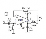
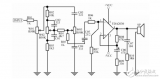
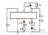
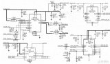
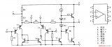
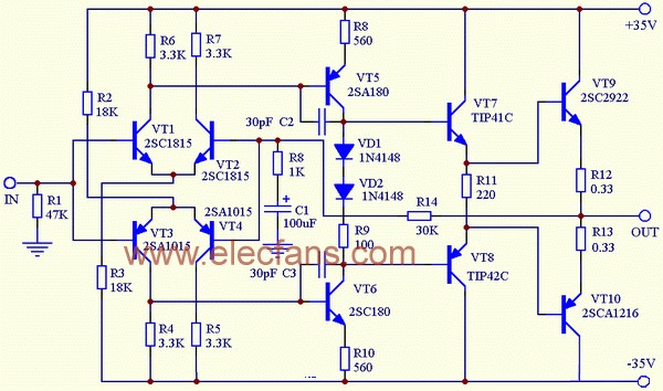
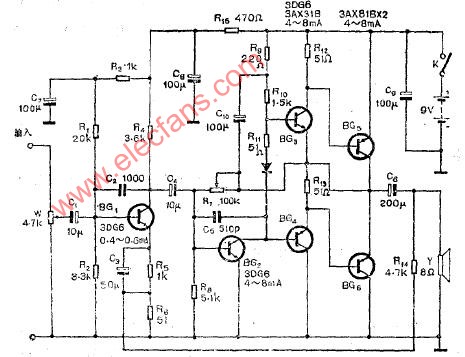
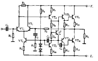
Figure 3 is a commonly used power amplifier circuit in the radio. Its static working current is adjusted by the bias resistor R8. Generally, the total static collector current of the two tubes is 4 ~ 8mA. R10 is a negative feedback resistor, used to reduce distortion and reduce the "pairing" requirements of the transistor. In order to reduce the loss of the input signal on the two resistors R9 and R10, their resistance values ​​are relatively small. Capacitor C7 is used to improve sound quality.
 |
 |
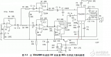
In order to reduce distortion, the circuit must also provide quiescent current for the transistor. Resistor R73 is not only a part of the load of the front-stage voltage amplifier BG12 (not shown in the figure), but also the base bias resistance of the complementary power amplifier tube. When the output current of BG12 passes through R73 and diode BG39, the voltage drop generated on them is the sum of the bias voltages of the emitter junctions of BG13 and BG14. The magnitude of this voltage determines the working current of the complementary power amplifier tube. When the resistance value of R73 changes or the working current changes through it, it will affect the working point of the power amplifier tube. This should be paid attention to when adjusting.
Diode BG39 in series with R73 is used to stabilize the static operating point of the complementary tube. It is a silicon diode, which produces a voltage drop of about 0.7V when current passes through it. When the ambient temperature increases, the forward resistance of the diode decreases, and the voltage drop across the diode also decreases, which reduces the base bias voltage of the complementary tube, counteracting the trend of increasing operating current due to temperature rise. Resistor R74 is connected in parallel with the diode to prevent the power amplifier tube from being burned due to excessive current when the diode is broken and damaged.
In the circuit, the capacitor C63 plays a very important role. Because for the audio signal, the power supply can be regarded as a path, so the collector of BG13 is "AC contact ground" like BG14. If there is no C63, the signal will be sent between the base and collector. This kind of "common collector connection" with the collector as the common terminal of the input and output signals has a low gain and is not suitable for use in power amplifier circuits. After it is connected to C63, it can also be regarded as a path for the audio signal, so the input signal is added to the base and emitter for BG13 through R72; for BG14, it is added to the base and emitter through R73 and R72. In this way, the circuit becomes a "common emitter connection" with much higher gain, which greatly increases the output power. The function of the resistor R71 is to play an isolation role, so as not to make the collector of the DG13 and the emitter short-circuited.

Follow WeChat

Download Audiophile APP

Follow the audiophile class
related suggestion
This article mainly introduces the dual power supply automatic switching circuit diagram (TDA2030 / power amplifier / dual power supply circuit). In the power amplifier circuit ...
The power amplifier circuit that omits the output transformer is usually called an OTL (Output TransformerLess) circuit.
In the field of audio, people have always maintained the position of Class A amplifiers. It is considered that the sound of Class A amplifiers is the most fresh and transparent, with high fidelity. However, Class A ...
The amplifier has AC amplifier and DC amplifier. AC amplifiers can be divided into low frequency, medium source and high frequency according to frequency; the output signal strength is divided into voltage amplification ...
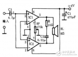
In the picture, IC1 and IC2 are two sets of LM386, which are connected into OCL circuit. C1 plays the role of power supply filtering and decoupling, C3 is the input coupling ...
RF LNA design requirements, low noise amplifier (LNA) as the first stage of the RF signal transmission link, its noise figure characteristics determine the entire radio ...

Radio frequency refers specifically to electromagnetic waves with a certain wavelength that can be used for radio communications. The high-frequency circuit used to generate radio frequency becomes a radio frequency circuit, which is basically composed of passive components ...
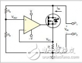
The self-bias circuit is relatively simple, but when the static operating point is determined, VGS and ID are determined, so the range of R selection is very small.
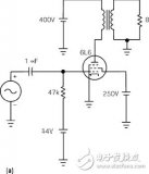
6L6 is a beam power tube with cathode, control grid, curtain grid, suppression grid and anode. The suppression grid is actually lifted by two bunching plates ...
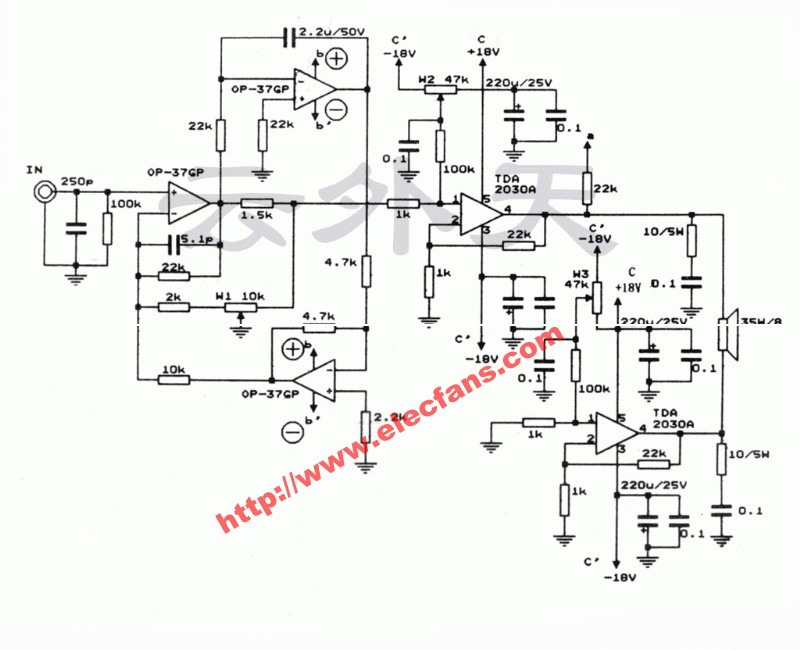
The TDA2030A power amplifier board is powered by an attenuating tone control circuit and a TDA2030A amplifier circuit and power supply controlled by high and low ...
However, in some cases, when the load is a resistor, its characteristics must be studied. The use of high-power potentiometers may be a high-cost solution without cost-effective ...
As shown in the figure is the auxiliary audio power amplifier circuit of LM4730. The audio input signal is added to the LM47 through the potentiometers Rv, CIN, RB ...
Hearing aid (Hearing Aid) is a help hearing impaired people to improve hearing impairment, and thus improve the ability to communicate with others ...
Here is a BTL power amplifier circuit without debugging, high fidelity, and low cost, and you can choose the final power amplifier integration according to your own situation ...
This circuit is an OCL power amplifier circuit composed of a low-power integrated power amplifier LM386. The circuit structure is simple, easy to debug, and very suitable for self-made ...
Cats are the natural enemies of mice, and it is an effective method to use electronic devices to simulate the sound of cats. Because it is an electronic device, the meow sound can be large or small, fast or ...
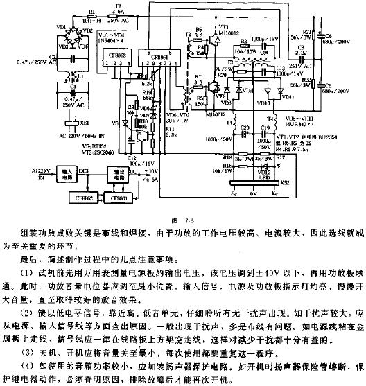
The light-controlled street lamp circuit is composed of a power circuit and a light-controlled circuit. The power circuit is composed of a power transformer T, a rectifier diode VDl-VD4 and a filter capacitor ...
The TDA2030A power amplifier board is powered by an attenuating tone control circuit and a TDA2030A amplifier circuit and power supply controlled by high and low ...

The speaker amplifier, gyroscope, compass and other circuits of the Apple iPhone 4S mobile phone are amplified by the speaker audio power chip U702 (T ...
The wireless energy transfer charger transmits the power wirelessly to the bulb (battery) through the coil. The wireless energy transfer charger is composed of energy sending unit and energy receiving ...
The small power amplifier made with TDA2009A introduces a 10 + 10W stereo amplifier made with TDA2009A power amplifier integrated circuit ...
1. The role of the connector The connector, also known as the connector, is mainly used to provide convenient electrical plug-in connection in electronic products and power equipment. It should be widely used ...

LM1877 is a single-chip dual-channel audio power amplifier, each channel can output 2W continuous average power, driving 8Ω load, requiring few external elements ...
LM386 is a universal power amplifier circuit.
Circuit principle: POWON-HE328 50W * 2 Class A push-pull power amplifier to ground, refer to the HARMAN / K ...
The compact disc player, pure power amplifier and high-fidelity speakers are the most basic combination of sound. For general working-sound audio enthusiasts, the price is more expensive
This circuit is composed of simple components and the structure is easy to understand.
Hi-Fi power amplifier circuit (with BOM) This is a simple low success rate amplifier. There are 5 ways you can complete her, just like a chart ...
Interpretation of basic knowledge of notebooks-There are several common discussions about power supply voltage, power supply, power supply and load matching ...
Interpretation of the basic knowledge of notebooks-power adapter on power supply voltage, power supply, power supply and load
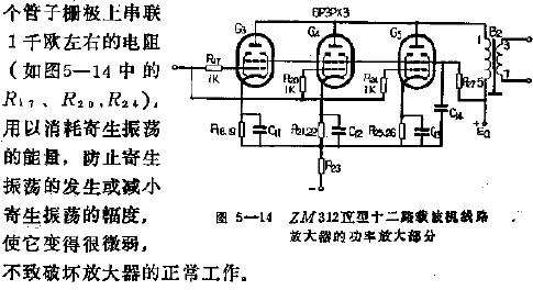
The circuit of the power amplification stage of the ZM312 12-channel carrier line amplifier is shown as the ZM312 12-channel carrier line amplifier ...
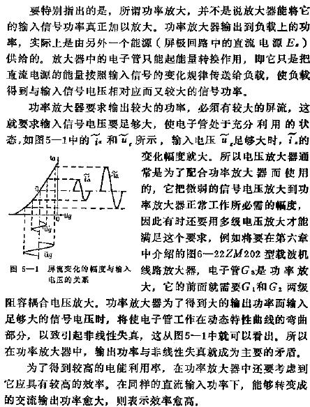
What is a power amplifier? In communication equipment, the last stage of a multi-stage amplifier always carries a certain load, for example, to make the speaker emit sound, ...
Transistor power amplifier circuit: the picture shows the power amplifier circuit matched with the electronic piano
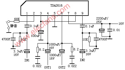
TDA2616 power amplifier circuit diagram
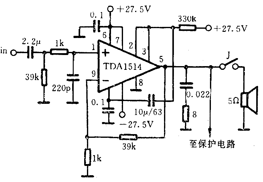
TDA1514 power amplifier circuit diagram
TA8223 / TA8223K dual-channel power amplifier circuit
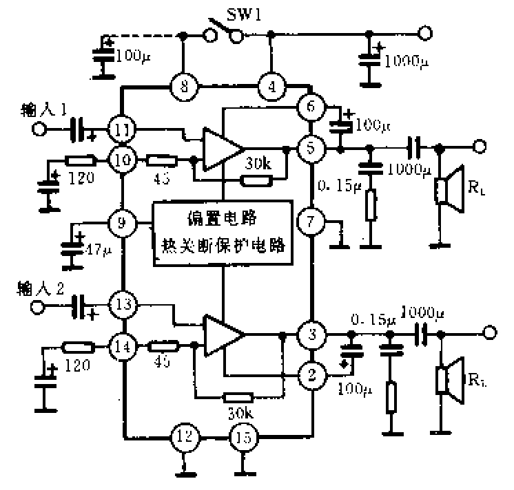
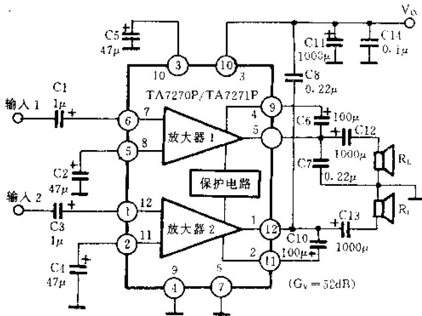
TA7270 / TA7270P power amplifier circuit
Typical OTL power amplifier circuit diagram
Introduction of LM386 Audio Power Amplifier LM386 is an audio power amplifier produced by National Semiconductor, mainly used in low voltage consumption ...
Push-pull power amplifier circuit diagram
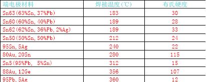
Basic knowledge of electrode materials The internal and external electrodes are an important part of the capacitor. The internal electrode is mainly used to store charge, its effective area size and ...
Power amplifier interface circuit
Class B push-pull power amplifier
The power amplifier tube is a key device in the audio power amplifier. Now let's compare the genuine and the fake ...

The electret microphone has the characteristics of small size, simple structure, good electro-acoustic performance and low price. It is widely used ...
Transformers are used in almost all electronic products. Its principle is simple but according to different ...
Basic knowledge of power MOSFET
1. Available on the market
Transformers are used in almost all electronic products. Its principle is simple but according to different use occasions (different uses), the winding process of the transformer will ...
All communication between computers through the computer network involves transmission ...
1 antenna
![[Photo] Basic knowledge of antenna](http://i.bosscdn.com/blog/20/06/41/5211351344.jpg)
'+ data.data.username +' '; dom + ='
ZGAR TWISTER Disposable
ZGAR electronic cigarette uses high-tech R&D, food grade disposable pod device and high-quality raw material. All package designs are Original IP. Our designer team is from Hong Kong. We have very high requirements for product quality, flavors taste and packaging design. The E-liquid is imported, materials are food grade, and assembly plant is medical-grade dust-free workshops.
Our products include disposable e-cigarettes, rechargeable e-cigarettes, rechargreable disposable vape pen, and various of flavors of cigarette cartridges. From 600puffs to 5000puffs, ZGAR bar Disposable offer high-tech R&D, E-cigarette improves battery capacity, We offer various of flavors and support customization. And printing designs can be customized. We have our own professional team and competitive quotations for any OEM or ODM works.
We supply OEM rechargeable disposable vape pen,OEM disposable electronic cigarette,ODM disposable vape pen,ODM disposable electronic cigarette,OEM/ODM vape pen e-cigarette,OEM/ODM atomizer device.


ZGAR TWISTER Vape,ZGAR TWISTER Vape disposable electronic cigarette,ZGAR TWISTER Vape pen atomizer ,ZGAR TWISTER Vape E-cig,TWISTER Vape disposable electronic cigarette
Zgar International (M) SDN BHD , https://www.zgarvapor.com