As a key component of modern cars, the steam harness includes thousands of assembly elements that connect various electronic systems together so that they can work together. Any small faults in the wiring harness may affect the entire system. However, in order to cope with the increasing demand for electronic systems inside vehicles, the complexity of automotive wiring harnesses is also increasing, so we urgently need to quickly and easily detect open and short circuits. Line diagnosis is very important throughout the life of the vehicle. Starting from the installation phase, diagnosing and repairing line faults can cause severe manufacturing delays. During the operation phase, diagnosing and repairing circuit faults may lead to an increase in the number of car repairs, thereby significantly increasing the manufacturer's warranty costs.
Active safety systems, including lane detection and parking assist systems (front-view and rear-view cameras), and infotainment systems (including navigation and rear-seat entertainment), are car electronic systems that people pay more attention to. For these systems to operate efficiently, the video data transmitted over the cable from any corner of the car must be able to be reliably transmitted to the driver and passengers. Cable health is essential to maintain the normal operation of these systems.
This paper presents a circuit concept that can provide reliable and cost-effective technology for diagnosis on video and audio transmission lines in automotive applications.
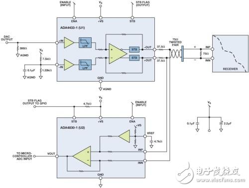
The circuit shown in Figure 1 can effectively detect battery short circuit (STB), short circuit to ground (STG), open circuit and short circuit faults. This circuit uses the ADA4433-1 (U1) fully integrated video reconstruction filter as part of the video transmission signal chain, and also uses the ADA4830-1 (U2) high-speed differential amplifier as the detection circuit. The ADA4433-1 has a built-in high-order filter with a -3dB cut-off frequency of 10MHz, which provides 45-dB suppression at 27MHz and an internal fixed gain of 2V / V. It has excellent video characteristics, provides overvoltage protection (OVP) and overcurrent protection (STG) on the output, and low power consumption. The ADA4830-1 provides an attenuation gain of 0.50V / V, and also provides a fault detection output flag to indicate whether there is an overvoltage condition on its input. It provides input overvoltage protection up to 18V, with a wide input common-mode voltage range and excellent ESD stability.
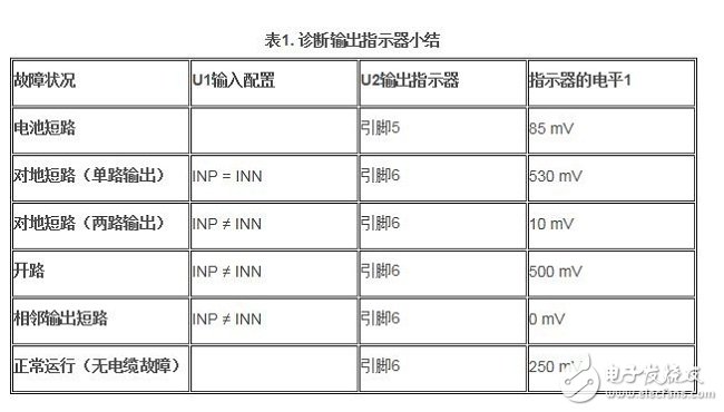
In the example circuit shown in Figure 1, U1 stands for differential output buffer, which can transmit video signals from the rear-view camera or engine control unit (ECU) to the receiver. The input is usually driven by a CMOS imaging element or video encoder. The main function of U1 is to provide active filtering function (reconstruction) and drive the transmission of video signals to the display screen through the cable. The input of U2 is connected across the output of U1 to provide the fault detection functions listed in Table 1, which will be explained in the following paragraphs.

Figure 1. Line diagnostic circuit using ADA4433-1 (U1) and ADA4830-1 (U2).
Battery short-circuit fault detection
Both U1 and U2 have integrated battery short-circuit detection and STB output flags. In the event of a battery short circuit, the output flag of U2 will signal a logic low state, and the general-purpose input / output (GPIO) port of the microcontroller can easily read this signal.
Ground fault detection (single output)
Connect the positive input (INP) of U1 to the negative input (INN). The differential output between + OUT and -OUT should be 0V. If any output is shorted to ground, the differential voltage at the output of U2 should be greater than 500mV.
Ground fault detection (two outputs)
Set the positive input (INP) of U1 to 0V. The differential output between + OUT and -OUT should be approximately 1V. If both outputs are shorted to ground, the differential voltage at the output of U2 is approximately 0V.
open circuit
Set the positive input (INP) of U1 to 0V. The differential output between + OUT and -OUT should be approximately 1V. If there is a short open connection, the differential voltage generated at the output of U2 is approximately 500mV.
Adjacent output short circuit
Set the positive input (INP) of U1 to 0V. The differential output between + OUT and -OUT should be approximately 1V. If the two outputs are shorted together, the differential voltage generated at the output of U2 is approximately 0V.
Normal operation (no cable fault)
Set the positive input (INP) of U1 to 0V. The differential output between + OUT and -OUT should be approximately 1V. The differential voltage generated at the output of U2 is approximately 250mV.

Author: ADI company high-speed signal conditioning unit Marketing Engineer Don Nisbett
What is Car Ethernet
Car Ethernet is a new local area network technology that uses Ethernet to connect the electronic unit in the car. Unlike traditional Ethernet, which uses 4 unshielded twisted pair cables, car Ethernet can achieve a transmission rate of 100Mbit/s or even 1Gbit/s on a single pair of unshielded twisted pair cables. At the same time, it also meets the requirements of the automotive industry for high reliability, low electromagnetic radiation, low power consumption, bandwidth allocation, low latency and synchronous real-time. The physical layer of on-board Ethernet uses BroadRReach technology, and BroadR-Reach's physical layer (PHY) technology has been standardized by the One-pair Ethernet Alliance (OPEN). Therefore, it is sometimes called Broad RReach (BRR) or OABR (Open Alliance BroadR-Reach). The MAC layer of vehicle Ethernet adopts the IEEE 802.3 interface standard and seamlessly supports widely used high-level network protocols (such as TCP/IP) without any adaptation.
On-board Ethernet protocol architecture
Vehicle-borne Ethernet and its supported upper-layer protocol architecture are shown in Figure 1. Vehicle-borne Ethernet mainly involves OSI layer 1 and Layer 2 technologies, while vehicle-borne Ethernet also supports AVB, TCP/IP, DOIP, SOME/IP and other protocols or application forms.
On-board Ethernet framework
Among them, AVB is an extension of traditional Ethernet functions, which enhances the real-time performance of traditional Ethernet audio and video transmission by adding precise clock synchronization, bandwidth reservation and other protocols, and is a network audio and video real-time transmission technology with great development potential. SOME/IP (Scalable Service-Oriented MiddlewarE on IP) specifies the video communication interface requirements for vehicle camera applications, which can be applied to the field of vehicle cameras, and realizes the mode control of driver assistance cameras through apis.
As an extension of AVB protocol, Time-Sensitive Networking (TSN) introduces related technologies of time-triggered Ethernet, which can efficiently realize the transmission of automotive control information. In addition, the on-board Ethernet of the 1Gbit communication standard also supports Power Over Ethernet (POE) function and Energy-Efficient Ethernet (EEE) function. The POE function provides power for connected terminal devices while transmitting data through twisted pair cables, eliminating the need to connect external power cables to terminals and reducing the complexity of power supply.
On-board Ethernet standardization
In terms of in-vehicle Ethernet standardization, the IEEE802.3 and IEEE802.1 working groups, AUTOSAR, the OPEN Alliance and the AVnu Alliance have played a major role in promoting it.
The IEEE802.3 local area network standard represents the mainstream Ethernet standard in the industry, and the on-board Ethernet technology is developed on the basis of IEEE802.3, so the IEEE is currently the most important international standardization body for on-board Ethernet. In order to meet the requirements of the car, it involves the development of a number of new specifications and the revision of the original specifications within the two working groups of IEEE802 and 802.1, including PHY specifications, AVB specifications, and single-wire to data line power supply. In addition, AVB related to AV transmission, timing synchronization and other specifications also need to be standardized by other technical committees of IEEE, such as IEEE1722 and IEEE1588.
OPEN Alliance
The OPEN Industry Alliance was launched in November 2011 by Broadcom, NXP, and BMW to promote the application of Ethernet-based technology standards to in-car connectivity. The main standardization goal is to develop a 100Mbit/s BroadR-R physical layer standard and develop OPEN interoperability requirements.
AUTOSAR
AUTOSAR is a consortium of automotive manufacturers, suppliers, and tool developers that aims to develop an open, standardized automotive software architecture, and the AUTOSAR specification already includes the automotive TCP/UDP/IP protocol stack.
AVnu
The AVnu Alliance was formed by Broadcom in collaboration with Cisco, Harman and Intel to promote the IEEE 802.1 AVB standard and the Time Synchronization Network (TSN) standard, establish a certification system, and address important technical and performance issues such as precise timing, real-time synchronization, bandwidth reservation, and traffic shaping.
Vehicle Router,Vehicle 4G Router,Vehicle 4G Wireless Router,Vehicle Wifi Router
Shenzhen MovingComm Technology Co., Ltd. , https://www.movingcommtech.com