The article first briefly introduces the HTC network monitoring system, and then proposes a 3G-based HFC network (optical fiber coaxial cable) monitoring system solution, which can solve the NAT (network address translation) penetration brought by 3G, and finally The four HFC system applications based on GOOGLE electronic maps are elaborated in detail. This design has an irreplaceable role in preventing low-cost illegal signal entry and ensuring smooth broadcasting.
1 Introduction of HFC network monitoring system
With the continuous development of the triple play business. HFC monitors the security and stability of the network, preventing illegal signal entry, improving service quality, and meeting the development of triple-play services. At present, the monitoring equipment of the HFC network has the following characteristics:
(1) The unidirectional HFC network and the bidirectional network coexist at the same time. At present, most of the domestic network design is still based on the unidirectional network.
The two-way network is mainly concentrated in areas with a certain economic foundation and strong demand for digital services, such as high-end residential areas, office buildings, and hotels. The design of HFC networks in urban villages and urban-rural junctions with a large number of users is still centered on the popularization of digital TV networks.
(2) The bidirectional channel using the HFC network cannot improve the monitoring reliability because the bidirectional network itself relies on the HFC network as the transmission medium. Once the network is abnormal, the monitor using the two-way channel of the HFC network itself will lose the return channel and cannot transmit accurate information from the monitoring point back to the front end. The front end can only judge the failure of the monitor, but cannot judge the network status, which affects the accuracy of the system's judgment on network security and network status.
(3) There is a bandwidth bottleneck in the currently used wireless access method. Currently, the use of Wi-Fi and other large-bandwidth wireless methods has low coverage and cannot form a scale effect. However, due to bandwidth problems, the GPRS method cannot transmit a large number of screenshots in real time, and cannot effectively determine whether the network has been invaded by illegal signals.
2 HFC network monitoring system solution
2.1 System topology
Figure 1 is the topology diagram of the system solution. The system consists of a front-end central server cluster and a terminal HFC network monitor. The central server cluster is installed in the front-end computer room, and the HFC network monitor is installed in the key nodes of the HFC network, such as the optical machine, building, and dry place. Both use the IP (Internet Protocol) channel of the 3G network for data exchange.

Figure 1 HFC network monitoring system topology
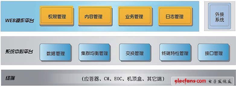
Figure 2 is the front-end central server cluster architecture, the platform is divided into Web (Internet site) operating platform and central platform module. The Web operation platform provides a graphical interface between the user and the system kernel. According to functional requirements, it is divided into four functional modules: rights management, content management, business management, and log management. Users can operate and manage the system by logging into the Web platform. The system center platform provides data management, cluster balance management, switching management, terminal feature management, and interface management.

Figure 2 HFC network monitoring system architecture
2.2 Monitor design
Figure 3 is a schematic diagram of the system monitor design. The monitor receives the signal of the HFC network through the high-frequency head, and obtains the signal quality and the digital information of the signal source. The CPU (central processing unit) is connected to the 3G module through the USB module. The HFC signal quality data obtained by the monitor and the HFC program image being broadcast are sent to the 3G network through the 3G module, and then transmitted back to the central server.

Figure 3 Monitor design
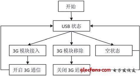
Figure 4 shows the software flow for the 3G module of the monitor. The monitor uses a multi-threaded design pattern. After the system initializes the CPU's USB hardware interface.
The USB monitoring thread will continuously access the USB status register of the CPU to detect whether there is a USB hardware change event. If there is a 3G module hardware access event found in the USB status register. The system will look for the driver of the 3G module and open the application thread for 3G communication. The system can start 3G communication through this thread and enable the HFC network monitoring thread. When the USB status register shows that the event is 3G communication removal, the system will delete the HFC network monitoring thread.

Figure 4 Software flow of the 3G module of the monitor
72V Battery Pack ,Lithium Ion Battery Pack,Lithium Battery Pack,Battery Power Pack
Zhejiang Casnovo Materials Co., Ltd. , https://www.casnovonewenergy.com