In the past, automotive electronic systems seldom used capacitive sensors because they were considered difficult to control, difficult to read, prone to ageing, and susceptible to temperature. Capacitive sensors, on the other hand, have attractive features such as moderate manufacturing costs, simple form factor, and low power consumption, which powers their use. With the advent of new measurement technologies, the number of capacitive sensors used in automobiles has increased dramatically.
This article refers to the address: http://
challenge
Macroscopically, to analyze a capacitive sensor, it is usually necessary to convert its capacitance to another physical variable such as voltage, time or frequency. Microscopically, capacitive sensors have been used in automobiles for a long time. Microelectromechanical acceleration sensors are based on this principle. These sensors are often used to detect charge transfer.
A new method for detecting capacitance is to use an adapted sigma-delta converter input stage to detect unknown capacitance and convert it to a digital value. This article will describe this approach to using capacitive-to-digital converters (CDCs) and several capacitive sensor principles that can be used in automotive electronics design. Finally, this article outlines another alternative.
Capacitance to digital converter
In order to visualize the CDC method, we must first understand the principle of Σ-Δ conversion. Below is a simplified sigma-delta converter circuit diagram.
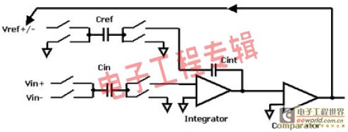
In order to clearly understand how it works, we first look at the input of the integrator, which must maintain a zero value over a longer time interval, and small short jumps will be converted to ramps. The zero mean can be achieved by raising the output of the reference branch to the same level as the input branch, which in turn is affected by the output of the comparator. At logic 1, the reference voltage is switched to the subsequent capacitor.
The capacitor is reversely charged and applied to the integrator, causing a negative reference voltage to be applied to the integrator. The high voltage at the input thus causes a large amount of logic 1, which in turn acts frequently on the negative reference voltage. The density of 1 is converted to a digital value by a post digital filter. A typical sigma-delta converter compares the unknown voltage to a known voltage and does so using two known (usually equal) capacitors.
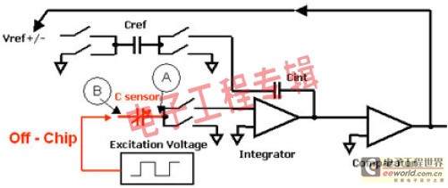
In fact, the charge is compared, so if both voltages are of a known value (in this case an equal voltage is used), the capacitance can be compared by Q=C*V. A synchronous voltage signal must also be applied to the input branch as shown in the capacitance to digital converter shown below.
This method has several advantages. Because of their close relationship with sigma-delta converters, their well-known characteristics can be modified and employed, including: high noise rejection, high resolution at relatively low frequencies, and the ability to achieve high accuracy cost-effectively.
All sigma-delta converters have similar input structures, almost without exception, so that special structures can be modified to suit specific measurement tasks, such as: extremely low current input, highest precision or higher. Cut-off frequency.
If we look closely at the above picture, we can find more advantages. The parasitic capacitance has no effect on the initial approximation. The parasitic capacitance that leads to zero at node A has a zero potential. Node B is not at zero potential, but a defined low-impedance potential is fed into it, so the parasitic capacitance at that node will be charged to an average value that does not affect the measurement. The parasitic capacitance from node A to node B is always in parallel with the measurement unit and always appears as an offset.
Existing capacitance to digital converters can provide very high performance. For example, Analog Devices' AD7745 achieves 24-bit resolution and 16-bit accuracy.
Capacitive sensor
In the past, capacitance analysis systems required relatively large measurement capacitances and large capacitance changes when touched. Requiring large enough changes often causes problems for sensor manufacturers, and smaller capacitive sensors do not. For example, a typical 150 pF humidity sensor is not only very expensive (because it has a large capacitance), but is also more prone to errors and has a lower long-term stability.
The capacitance of a capacitor can be calculated based on its structure:
C = εoεr A/d
Where εo is the dielectric constant of free space, εr is the dielectric constant of the material, A is the area of ​​the available metal plate, and d is the distance between the two electrodes. With a few exceptions, such as pressure sensors, all other capacitive sensors measure the change in capacitance using changes in the surface of the metal plate or dielectric. Most sensors can be divided into two categories: one is the change in the geometrical area of ​​the metal plate, such as liquid level sensing or displacement sensor; the other is the change in the dielectric constant εr of the material, such as proximity sensor or humidity sensor.
Dielectric sensor
A typical example of a dielectric sensor is a moisture sensitive sensor that uses a moisture sensitive polymer layer as a dielectric. As the humidity increases, more and more water molecules deposit, resulting in an increase in εr. Sensors that determine the purity of a liquid, such as petroleum or fuel, are essentially composed of two fixed plates that themselves constitute a dielectric. The required liquid properties are determined empirically (ie, the moisture in the oil or fuel increases). Temperature plays a decisive role and must be reliably determined. Simple proximity sensors that determine dielectric changes often require the most sophisticated measurement electronics.
In most cases, the proximity sensor consists of two conductors on a printed circuit board with a very low dielectric constant (close to 1). If an object (such as a hand) moves into the electric field of the capacitor, the capacitance changes. The human body has a water content of more than 90% and therefore has a very high dielectric constant (about 50).
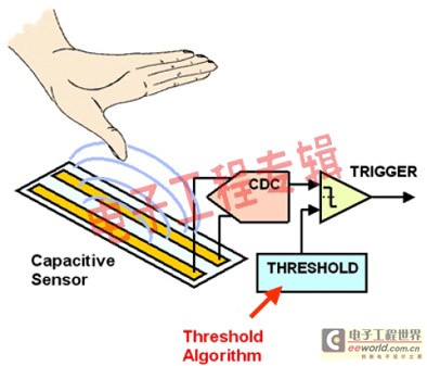
Non-contact switches are very easy to manufacture and support applications such as keyless ignition or power window anti-pinch. The core requirement of a keyless car is that the current input is as low as possible and the standard value is less than 100 uA. The sigma-delta converter has been optimized for many years in the industry, so it provides the right architecture.
Rain sensors can also be implemented in a similar way, are easy to produce and cost effective, and have the advantage of form factor. However, the traditional rain sensor based on optical refraction of water droplets has a very small effective area on the windshield glass, which reduces the sensitivity of the system and repeatedly causes problems with dry scraping and wiper failure.
Geometrically variable sensor
Examples of sensors that rely on geometric dimensional changes are pressure sensors, level sensors, and displacement sensors, all of which simply move the dielectric between the fixed plates. The pressure sensor uses two fixed-size plates as the diaphragm. When pressure is applied to the sensor, the distance between the plates changes due to elasticity.
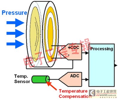
Due to thermal expansion, a temperature sensor is needed to measure the change in geometry. It is envisaged that one electrode is connected to the chip and the other electrode is connected to a casing made of metal or ceramic, so that the casing itself functions as a sensor. For example, ceramic housings can withstand very high pressures and aggressive media. Compared to traditional Wheatstone bridges, the main advantage of capacitive pressure sensors is their lower input current requirements, making them ideal for applications such as tire pressure control.
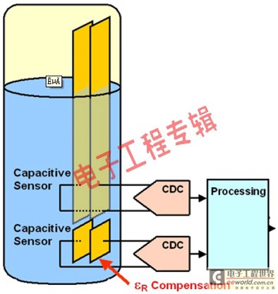
In the level sensor, a pair of fixed plates are immersed in the liquid to be tested. Manufacturers are able to implement printed conductors at very low cost. The second pair of plates are mounted in the bottom area to detect changes in the dielectric due to temperature or other effects, as shown in the following figure.
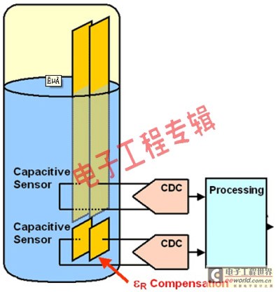
Among all methods, the Σ-Δ technique proved to be exceptionally effective. In many cases, digital filters that must be used can be used to achieve the desired dynamic behavior. For example, liquid level sensors require an extremely long time constant, while proximity sensors must adapt to changing environmental conditions (such as humidity sensors used to measure rainfall or icing).
Another alternative
There is also a technique that works in a completely different and slightly more complicated way. However, it can be used to measure complex impedances, including inductive, resistive/capacitive or resistive/inductive sensors. In this case, the sensor is excited by a very accurate known frequency, and direct digital synthesizer (DDS) technology is well suited for this application.
Calculate the real and imaginary parts of the impedance using the DDS method
Analysis of the response of the sensor recorded by flash analog to digital converter and fast Fourier. With the DDS method, the original phase position can be accurately known at any time. In the same way, the response to other frequencies can also be measured. From this it is possible to calculate the real and imaginary parts of the impedance and then output them via the digital bus. A full scan is only a few hundred milliseconds. The figure below illustrates the method.
The network analyzer circuit can be used for capacitive and inductive sensors, as well as sensors that record motion or measure the viscosity of liquids such as oil or transmission oil.
Conclusion
Capacitive sensors are reborn in automotive applications, and new applications have emerged in applications such as pressure, level, humidity, rainfall and proximity sensors. Σ-Δ technology provides a flexible solution to meet different dynamic and accuracy requirements, and supports sensor systems that require extremely low power requirements. CDC devices have been used in a variety of automotive applications and will be used in a wider range of applications.
Networking Keystone Jacks.China Cat5e Coupler Jack,Keystone Jack Short Body manufacturer, choose the high quality Cat5e Jack Short,Keystone Jack Unshield, etc, included keystone jacks for CAT6A, CAT6, CAT5E, and CAT3
Keystone jacks are snap in modules used to mount low voltage electrical connectors into a keystone wall plate, patch panel, face plate or surface mount box.
Our Keystone Jacks are available in 10 different colors for easy color-coded installations.
RJ45 port editing
1. Origin:
2. The name RJ stands for the registered jack and is the USOC (universal service ordering codes) code of bell system. USOC is a series of registered sockets and their wiring mode, which are developed by bell system to connect the user's equipment to the public network. FCC regulations control the application of this purpose. The FCC (Federal Communications Commission) issued a document on behalf of the U.S. government to specify RJ11.
3. RJ11 is the common name of the connector developed by Western Electric Co. Its shape is defined as a 6-pin connecting device. Originally called wexw, where x means "active", contact or needle. For example, we6w has all six contacts, numbered from 1 to 6. The we4w interface only uses four pins, the outermost two contacts (1 and 6) are not used, and we2w only uses the middle two pins. For RJ11, the information source is contradictory. It can be a 2 or 4-core 6-pin connector. What's more confusing is that RJ11 is not only used to represent the 6-pin connector, it also refers to the 4-pin version.
4. RJ45 and RJ11: different standards, different sizes
5. Due to the different sizes of the two (RJ11 is 4 or 6-pin, RJ45 is an 8-pin connection device), it is obvious that the RJ45 plug cannot be inserted into the RJ11 socket. However, it is physically feasible (RJ11 plug is smaller than RJ45 jack), which makes people think that they should or can work together. It's not. It is strongly recommended not to use RJ11 plug for RJ45 socket.
â’ because RJ11 is not internationally standardized, its size, insertion force, insertion angle, etc. are not in accordance with the international standard connector design requirements, so interoperability cannot be guaranteed. They even cause damage to both. Since the RJ11 plug is smaller than the RJ45 socket, the plastic parts on both sides of the plug will damage the metal pin of the inserted socket.
RJ - 45 port is our most common port, it is our common twisted pair Ethernet port
Because twisted pair is mainly used as transmission medium in Fast Ethernet, RJ-45 port can be divided into 10Base-T network RJ-45 port and 100base TX network RJ-45 port.
Among them, the RJ-45 port of 10Base-T network is usually identified as "eth" in the router, while the RJ-45 port of 100base TX network is usually marked as "10 / 100btx". This is mainly due to the fact that most products of Fast Ethernet router still adopt 10 / 100Mbps bandwidth adaptive.
The left figure shows the RJ-45 port of 10Base-T network, while the right figure shows the RJ-45 port of 10 / 100base-tx network. In fact, the two RJ-45 ports are exactly the same in terms of the port itself, but the corresponding network circuit structure in the ports is different, so they can not be connected casually.
Definition of RJ45 interface pin signal
Ethernet 10 / 100Base-T interface:
1 TX + tranceive data +
2 TX - tranceive data -
3 RX + receive data +
4 N / C not connected
5 N / C not connected
6 RX - receive data
7 n / C not connected
8 N / C not connected
Ethernet 100base-t4 interface:
1 TX_ D1 + tranceive data +
2 TX_ D1 - tranceive data
3 RX_ D2 + receive data +
4 BI_ D3 + bi directional data +
5 BI_ D3 bi directional data
6 RX_ D2 - receive data
7 BI_ D4 + bi directional data +
8 BI_ D4 bi directional data
Note: RJ45 interface adopts differential transmission mode, TX + and TX - are a pair of twisted pair, which can reduce interference when twisted together.
Cat5e Coupler Jack,Keystone Jack Short Body,Cat5e Jack Short,Keystone Jack Unshield
ShenZhen Antenk Electronics Co,Ltd , https://www.antenkcon.com