The function of GPIO is simply that it can be configured as input or output according to your needs. However, when configuring GPIO pins, you will often see two modes: open-drain, open-drain, and push-pull.
Push-Pull push-pull output
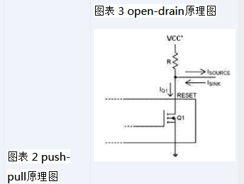
The output device means that a pair of complementary MOSFETs are integrated inside the output pin. When Q1 is turned on and Q2 is turned off, it outputs a high level; when Q1 is turned on and Q2 is turned on, it outputs a low level.
Push-pull output, in fact, uses two transistors inside, here called top transistor and bottom transistor. The corresponding level is output by the corresponding transistor of the switch. The top transistor is turned on (the bottom transistor is turned off), the output is high; the bottom transistor is turned on (the top transistor is turned off), and the output is low. Push-pull is capable of sink current and source current. It may or may not have another state: a high impedance state. No additional pull-up resistors are required unless Push-pull needs to support an additional high impedance state.
Open-Drain open drain output
An open drain circuit is a circuit that uses the drain of a MOSFET as an output. Refers to an N-channel MOSFET (Q1) between the internal output and ground. These devices can be used for level shifting applications. The output voltage is determined by Vcc'. Vcc' may be greater than the input high level voltage VCC (up-translate) or lower than the input high level voltage VCC (down-translate).
Open-drain output is less than the top transistor of push-pull, only the bottom transistor. (As in push-pull) When the bottom transistor is off, the output is high. There is no way to output a high level here. To output a high level, an external pull-up resistor must be connected. Open-drain can only sink current. If you want to source current, you need to add a pull-up resistor.
Foreigner understanding
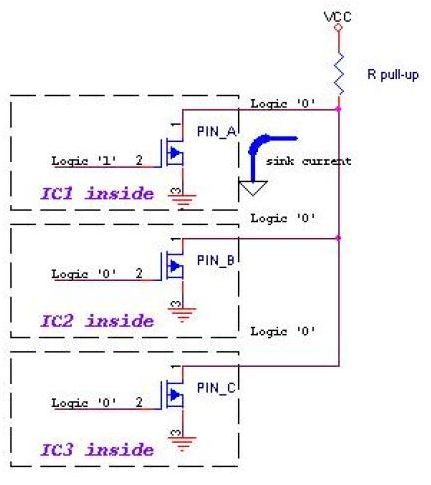
The common GPIO mode can be configured as open-drain or push-pull. In specific implementation, it is often configured as open-drain or push-pull by configuring certain bits of the corresponding register. When we set a bit of the GPIO configuration register through the CPU, the internal implementation of the GPIO hardware IC will turn the corresponding top transistor on or off. Correspondingly, if it is set to open-d mode, it is necessary to implement a pull-up resistor, and it can also output a high level. Therefore, if the internal hardware itself contains the corresponding pull-up resistor, the corresponding pull-up resistor will be turned off or on. If there is no corresponding pull-up resistor inside the GPIO hardware IC, then you must provide the corresponding external pull-up resistor in your hardware circuit. The advantage of the push-pull output is that it is fast because the line is driven in two ways. The line with the pull-up resistor, even if the voltage is raised at the fastest speed, the fastest R × C time. Where R is the resistance and C is the parasitic capacitance, including the capacitance of the pin and the capacitance of the board. However, the relative disadvantage of push-pull is that it often consumes more current, that is, the power consumption is relatively large. The current consumed by open-drain is relatively small, limited by resistor R, and R can't be too small, because when the output is low, a lower translator is needed, which means higher power consumption. (This paragraph: original the following transistor has to sink that current when the output is low; that means higher power consumption.) And one of the benefits of open-drain is that you allow cshort (?) multiple open-drain circuits A common pull-up resistor is called a wired-OR connection. In this case, the output can be low by pulling down the pin of any IO. In order to output a high level, all of them output a high level. This logic is a "wire-and-wire" function that does not require an additional gate circuit to implement this part of the logic.
Figure 4 open-drain "line and" function


advantage
Push-Pull push-pull output
(1) It can absorb current or cross current;
(2) Compared with the open-drain output, the high-low level of push-pull is determined by the power supply of the IC, and it is not easy to do logic operations.
Open-Drain open drain output
(1) Very useful for level shifting between various voltage nodes, can be used for Up-translate and down-translate conversion of various voltage nodes
(2) The pin pins of multiple open-drain outputs can be connected to a line to form a "logical" relationship, that is, the "line and" function. After any one becomes low, the logic on the open drain line is 0. . This is also the principle that I2C, SMBus and other buses determine the bus occupancy status.
(3) Reduce the driving inside the IC by using the driving capability of the external circuit. When the internal MOSFET of the IC is turned on, the drive current flows from the external VCC through R pull-up and the MOSFET to GND. Only a very low gate drive current is required inside the IC.
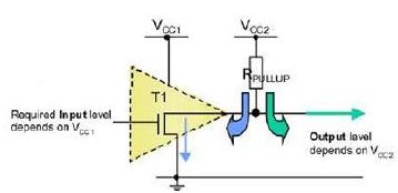
(4) The voltage of the pull-up power supply can be changed to change the transmission level: Figure 5 shows the principle of the open-drain output level. The logic level of the IC is determined by the power supply Vcc1, and the output high level is determined by Vcc2. This way we can control the output high logic with low logic.

Disadvantage
Push-Pull push-pull output
There can only be one push-pull output device on a bus;
In the CMOS circuit, the CMOS output should be called more suitable, because the push-pull output capability in CMOS cannot be made as large as the bipolar. Output capacity See the area of ​​the IC's internal output pole N tube P tube. Push-pull is the most used output stage design in CMOS circuits.
Open-Drain open drain output
The open-drain Pin is not connected to an external pull-up resistor and can only output a low level. When the output level is low, the N-channel transistor is turned on, so that a continuous current flows between Vcc' and GND through the pull-up resistor R and the transistor Q1. This affects the power consumption of the entire system. A larger value pull-up resistor can reduce the current. However, a large resistance value slows the rise time of the output signal. That is, the resistance of the pull-up resistor R pull-up determines the speed of the edge of the logic level transition. The larger the resistance, the lower the speed and the lower the power consumption. vice versa.
Strain/flex Reliefs And Grommets
the power Connectors we provide overmolding solutions and modular tooling.
We also offer to the OEM and distributor users a diversified line of strain / flex reliefs and grommets, such as Solid, Solid-Rib, Uniflex, Multiflex, in standard off the shelf or custom designs.
Overmolding the power connectors offers significant opportunities for cable improvements with higher pull strength not available with conventional backshells. Our technical staff is ready to help you from design and prototyping to small production run, assistance, and training.
Our team is ready to help with any of the following power connectors projects: overmolding mini fit jr. and mini-fit sr. connectors, , overmolded cables with micro fit terminations, sabre molded cable asemblies, amp duac overmolded power connectors, mate-n-lock power cables, power connector overmolding services, power connector molding, design and prototype of power cables across the board, small run molded power connecotrs , molded cable manufacturing, overmolding connectors for any power applications
Strain Reliefs And Grommets,Flex Reliefs And Grommets,Cable Strain Reliefs,Cable Flex Reliefs,Cable Grommets,Molded Strain Relief
ETOP WIREHARNESS LIMITED , https://www.wireharnessetop.com