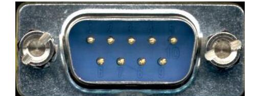
1 Carrier Detect DCD Received Line Signal Detector (Data Carrier Detect)
2 Receive data RXD Received Data
3 Send data TXD Transmit Data
4 Data Terminal Ready for DTR Data Terminal Ready
5 Signal Ground SG Signal Ground
6 Data Ready for DSR Data Set
7 Request to Send RTS Request To Send
8 Clear Send CTS Clear To Send
9 Ring Alert RI Ring Indicator
RS232 interface standardSerial communication interface standards have been used and developed, and there are already several. However, they have all been developed on the basis of the RS-232 standard. So, discuss mainly with RS-232C. The RS-232C standard is a communication protocol announced in 1969 that was jointly developed by the United States EIA (Electronic Industry Association) and BELL and other companies. It is suitable for communication with a data transmission rate ranging from 0 to 20000 b/s. This standard specifies the issues related to serial communication interfaces, such as signal line functions and electrical characteristics. Since communication equipment manufacturers all manufacture communication equipment compatible with the RS-232C standard, it is currently used as a standard and is widely used in microcomputer communication interfaces.
Before discussing the contents of the RS-232C interface standard, first explain two things:
terminal
First of all, the RS-232-C standard was originally developed for telecommunication connection data terminal equipment DTE (Data Terminal Equipment) and data communication equipment DCE (Data Communicate Equipment). Therefore, the formulation of this standard does not consider the application requirements of computer systems. However, it is now widely borrowed for the near-end connection standard between computers (more precisely, computer interfaces) and terminals or peripherals. Obviously, some of the provisions of this standard are inconsistent with the computer system, and even contradictory. With this understanding of the background, it is not difficult to understand where the RS-232C standard is incompatible with computers.
Send and receive
Secondly, the "send" and "receive" mentioned in the RS-232C standard are all based on the DTE position, not the DCE position. Because computer systems often transmit information between CPUs and I/O devices, both are DTEs, so both parties can send and receive.
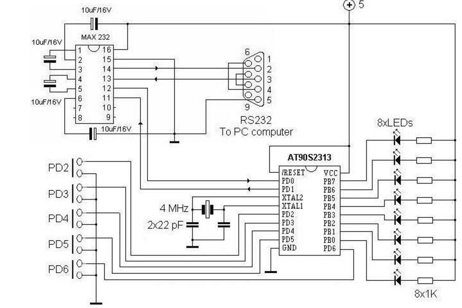
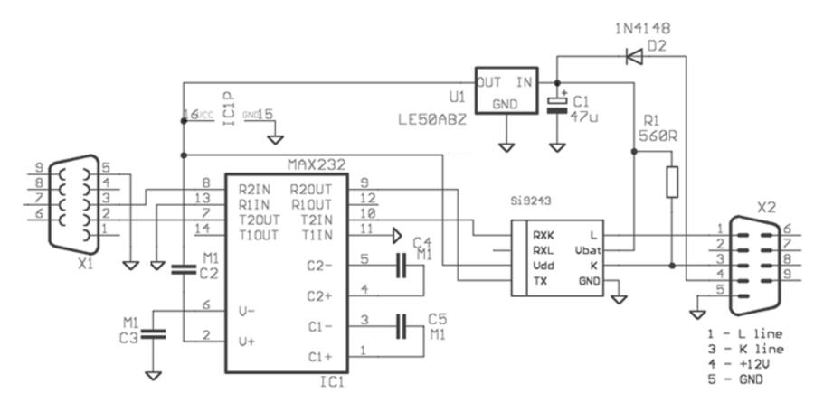
RS232 interface circuit diagram
Figure 1 Serial Circuit of AT90S2313 MAX232 AVR Microcontroller 
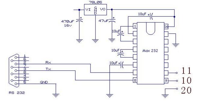
Figure 2 RS232 interface circuit
Judging the detailed method of RS232 chipThe serial port of the one-chip computer is TTL level, in actual application, need to change TTL level into RS232 level. There are many RS232 interface chips, the most famous of course is maxim's max232; many chips are fully compatible with this chip, such as LINEAR's LT1081, LT1181, HARRIS's ICL232, etc., are very famous and commonly used chips, LINEAR string Row interface conversion chips can often be seen in early circuit designs, but lately it seems to be rare. ICL232 is cheaper than MAX232.
Look at the block diagram of MAX232, need to pay attention to 2 points:
1) need external capacitor 0.1u capacitance, or 1u bile electrolytic capacitor or electrolytic capacitor, there is a 232 chip does not require an external capacitor, but because the circuit in the chip to achieve a capacitive effect is more difficult, so it is more expensive; so Generally use the external capacitor; the reason why the capacitor is needed is because the RS232 level is between -9V and +9V, and it needs the +10V and -10V required by the capacitor to convert the 5V voltage to Rs232 level; the circuit is called the charge. Pump, very image;
2) The logic of rs232 is exactly the opposite of TTL. In the block diagram, the logic between the input and output is reversed; for the TTL level, when there is no 232 signal sent, it is high; for RS232, at this time, the TX terminal is -8 ~ 9V voltage, relative At 0V, if there is a signal, it is a series of signals that are staggered from +9V to -9V. You can see the signal changes using an oscilloscope.
Using the above features, we can test the RS232 interface circuit is good or bad.
1) To determine if the chip is normal, see the block diagram of MAX232. Use a multimeter to measure 2 and 6 pins. As long as the voltage of pin 2 is between +8V and +9V and the pin 6 is between -8V~-9V, you can basically determine the chip. It is good;
2) When Rs232 is not signaling, look at the TX terminal voltage as Rs232 high, which is between -8V ~ -9V, when the signal is sent, the data is changing, this shows that this Rs232 port is good; this The method is also suitable for measuring the local serial port.
The early riser RS232 interface chip is MC1488 (sending), MC1489. MC1489 is only receiving, so it is a single 5V power supply; MC1488 requires positive and negative 12V power supply; but in the IPC board, the positive and negative power supply is not a problem, so in multi-port serial cards such as moxaC168, MC1488, MC1489 are still used, Cheaper and cheaper. Most of this chip, motorola.
RS232 drive capability is relatively strong, at least 10 meters or more, more courageous, used in 20 to 30 meters or more; then, the best use of shielded wire will be better.
Since the RS232 interface circuit is the only path for PCs and user development systems, it is the key to online debugging and downloading. In the development process of the user system, online communication failures often occur. There are many reasons that cause this phenomenon to occur, but the most likely is that the interface circuit works abnormally. To determine whether the RS232 interface circuit is working properly, check the RS232 communication one by one according to the following steps.
Is the 1V+ and V-pin voltage high enough (exceeds +8V and -8V respectively). If the voltage is low, the ADM202 chip may be damaged.
2R1IN pin presence of ± 12V pulse signal. If it exists, it indicates that the communication signal sent by the PC is normal.
Whether there is a +5V signal at the 3R1OUT pin. If it exists, it indicates that the ADM 202 receives the PC signal and works normally.
4T1IN pin existence +5V signal. If it exists, it indicates that the ADμC812 responds to the communication of the PC; otherwise there is a problem with the ADμC812, indicating that the ADμC812 is not working properly.
Whether there is a ±12V pulse signal at the 5T1OUT pin. If it exists, but ADμC812 still can not enter the online debugging state, then there is a problem with the serial interface cable between DB9 and PC.
1, using an oscilloscope to observe the MAX232's TXD waveform is a regular 0,1 waveform changes, but the amplitude is large; and RXD is not very regular 0,1 change, the rising edge appears cutting angle, the ramp voltage is slightly ups and downs. However, the TTL output is a regular 0,1 change waveform! !
2, using a multimeter to measure the voltage (VCC = 5V):
The second leg has a change of 8.7V-9.3V.
The sixth leg has a change of -8.4--(-9.0V);
1-3 feet is 4.9V-4.9V;
4-5 feet is 0.02V-3.9V

As shown in the above figure, we can use the following methods to determine whether there is a hardware problem in the serial port. Connect the pin 9 of the MAX232 to the ground and measure whether the DC output voltage is about 10V between pin 3 and pin 5 of the serial port. Voltage? Connect the 9th pin of MAX232 to 5V. Measure whether the DC voltage of -10V is output between pin 3 and pin 5 of the serial port. This can determine whether the MAX232 is in good condition and whether the serial cable is crimped at the crimped line.
B85 8-card mainboard, 8-card in-line motherboard platform (B85 8-card 1820U independent U+ new chassis 4 strong 5300 RPM fan /4 silent 3000 RPM optional +4G memory +128G solid state +2000W new power supply) compatible with all types of graphics cards in the market, stable performance, reasonable heat dissipation.
X79 Gpu Mining Case
Chassis weight: 4.5kg
Weight of chassis with fan: 5.5kg
Size:500*400*180mm
Multi graphics card case custom case
Motherboard bit: compatible with standard ATX motherboard
Hard disk bit: a 3.5-inch hard disk or a 2.5-inch hard disk
Power bit: ATX power installation size
Standard fan: 4 sets of 12038 fans,
Graphics card bit: supports up to 5 330mm long graphics cards
Chassis material: 1.0 mm cold plate full baking paint to prevent rust, anti-static effect!
tips: chassis products are bulky, heavy weight, and the express freight is very expensive. Buyers should consider buying them carefully to avoid unnecessary loss caused by return. If you don't understand, please communicate with customer service.
The fan of the product is double ball fan, 5300 RPM new violent fan, with noise of 65dB
B85 Gpu Case,B75 gpu case,gpu mining case,gpu case,GPU Server Case
Shenzhen YLHM Technology Co., Ltd. , https://www.ylhm-tech.com