CNC lathe is the abbreviation of digital program control lathe. It combines the characteristics of universal versatile lathe, precision lathe with high processing precision and special lathe with high processing efficiency. It is the largest in use and the most widely used in China. A CNC machine tool, accounting for about 25% of the total number of CNC machine tools (excluding technically modified lathes).
Classification of CNC lathes
1. Classification of CNC lathes
There are many classification methods for CNC lathes, but they are usually classified in a similar way to ordinary lathes.
(1) Classification by lathe spindle position
1) Vertical CNC Lathe Vertical CNC lathe is referred to as CNC lathe. The lathe spindle is perpendicular to the horizontal plane and has a circular table with a large diameter for clamping workpieces. This type of machine tool is mainly used to machine large and complex parts with large radial dimensions and relatively small axial dimensions.
2) Horizontal CNC lathe horizontal CNC lathe is divided into CNC horizontal guide horizontal lathe and CNC inclined guide horizontal lathe. The inclined rail structure allows the lathe to be more rigid and easy to remove chips.
(2) Classified according to the basic types of machined parts
1) Chuck type CNC lathes These lathes are not equipped with a tailstock and are suitable for turning discs (including short shafts). Most of the clamping methods are electric or hydraulic control, and the chuck structure has many adjustable jaws or no quenching (ie, soft jaws).
2) Top CNC Lathes These CNC lathes are equipped with a common tailstock or CNC tailstock. They are suitable for turning long shaft parts and discs and sleeve parts with a small diameter.
(3) Classification by number of tool holders
1) Single-turret CNC lathes Ordinary CNC lathes are generally equipped with various types of single-tool holders, such as four-station horizontal automatic indexing tool holder or multi-station turret type self-rotating tool holder. As shown in Figure 1.
Figure 1 Four-station automatic indexing tool holder
(2) Double-turret CNC lathes The configuration of the double-turrets of the lathes (that is, the distribution of the moving rails) may be parallel distribution as shown in Fig. 2a, or perpendicular to each other as shown in Fig. 2b, and the same rail structure. .
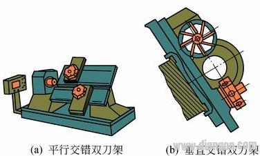
Figure 2 Combined automatic indexing tool holder
The composition and working principle of CNC lathe
1. The composition of the CNC lathe
Although there are many types of CNC lathes, they are generally composed of three main parts: lathe main body, numerical control device and servo system. Figure 3 is a block diagram showing the basic composition of a CNC lathe.
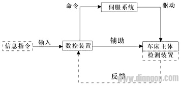
Figure 3 Block diagram of the basic composition of a CNC lathe
(1) Lathe body
In addition to some economical CNC lathes that basically maintain the traditional layout of ordinary lathes, most of the CNC lathes have been specially designed and shaped.
1) Spindle and spindle box
a) The rotation precision of the spindle CNC lathe spindle directly affects the machining accuracy of the parts; its power size and rotation speed affect the processing efficiency; its synchronous operation, automatic shifting and orientation quasi-stop requirements affect the automation of the lathe.
b) The spindle box has a numerical control lathe with automatic speed regulation function. The transmission mechanism in the spindle box has been greatly simplified; the CNC lathe with stepless automatic speed regulation (including directional stop) is used for mechanical transmission shifting and reversing. The mechanism has ceased to exist, and its headstock has become synonymous with "bearing seat" and "lubrication box"; for the modified (with manual operation and automatic control processing dual function) CNC lathe, it basically retains its original The headstock.
2) Guide rail
The guide rail of the CNC lathe is an important part to ensure the accuracy of the feed movement. It greatly affects the rigidity and accuracy of the lathe and the stability of the low-speed feed, which is one of the important factors affecting the quality of the parts. In addition to the traditional sliding guides (metal type), some CNC lathes have adopted plastic-coated guide rails. The new sliding guide rail has a small friction coefficient, and has good wear resistance, corrosion resistance and shock absorption, and the lubricating condition is also superior.
3) Mechanical transmission mechanism
In addition to the gear transmission in some of the headstocks, CNC lathes have been greatly simplified on the basis of the original ordinary lathe drive chain. If the hanging wheel box, the feed box, the slide box and most of the transmission mechanism are eliminated, only the vertical and horizontal feed screw transmission mechanism is retained, and the drive motor is added to the screw (a few lathes are not Add a gear pair that eliminates its backlash.
a) Spiral drive mechanism The spiral pair in the CNC lathe is a motion pair that converts the rotary motion output by the drive motor into a linear motion of the tool holder in the longitudinal and transverse directions. The components that make up the screw drive are typically ball screw pairs, as shown in Figure 4.
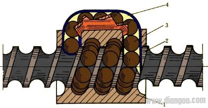
Figure 4 Ball Screw Pair
1 a nut 2 a screw 3 a ball 4 a ball circulation device
The frictional resistance of the ball screw pair is small, which can eliminate the axial clearance and pre-tightening, so the transmission efficiency and precision are high, the movement is stable, and the action is sensitive. However, the structure is more complicated and the manufacturing technology is higher, so the cost is also higher. In addition, it is more difficult to adjust the gap size by itself.
b) Gear pair. In the drive mechanism of many CNC lathes, a simple gear box (frame) is arranged between the drive motor and the feed screw. The main function of the gear pair is to ensure that the pulse equivalent of the lathe feed motion meets the requirements and avoid the adverse effects of the axial turbulence that the lead screw may have on the drive motor.
4) Automatic rotation of the knife holder
In addition to the automatic tool changer with a random tool change (with tool magazine) in the turning center, CNC lathes usually have automatic indexing tool holders with fixed position, and some lathes also have various forms of double tool holders.
5) Detection feedback device
The detection feedback device is an important part of the CNC lathe, which has a great influence on the processing precision, production efficiency and automation. The detecting device comprises two types: a displacement detecting device and a workpiece size detecting device, wherein the workpiece size detecting device is further divided into an internal size detecting device and an external size detecting device. The workpiece size measuring device is only used on a small number of high-grade CNC lathes.
6) Tool setting device
In addition to a few special-purpose CNC lathes, almost all types of automatic indexing tool holders are used for ordinary CNC lathes for multi-tool turning. In this way, the position of each knife's tool point on the tool holder, or the position relative to the fixed point of the lathe, requires tool setting, adjustment and measurement, and confirmation to ensure the quality of the part.
(2) Numerical control device and servo system
The main difference between a CNC lathe and a conventional lathe is whether it has two parts: a numerical control device and a servo system. If the detection device of the CNC lathe is equivalent to the human eye, then the numerical control device is equivalent to the human brain, and the servo system is equivalent to the human hands. In this way, it is not difficult to see the important position of these two parts in the CNC lathe.
a) Numerical control device
The core of the numerical control device is the computer and its software. It plays the role of “command†in the CNC lathe: the numerical control device receives various information sent by the machining program, and after processing and deployment, issues an execution command to the drive mechanism; In the process, the driving, detecting and other mechanisms simultaneously feed back relevant information to the numerical control device, so as to issue a new execution command after processing.
b) servo system
The servo system accurately executes the commands issued by the numerical control device, and completes various displacements required by the numerical control device through the drive circuit and the actuator (such as a stepping motor).
2. The working process of CNC lathe
The working process of the CNC lathe is shown in Figure 5.
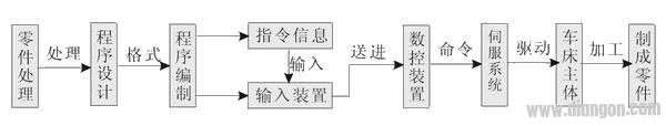
Figure 5 Working process of CNC lathe
(1) First, process analysis is performed according to the part processing pattern to determine the processing plan, process parameters and displacement data.
(2) Write the part processing program list with the specified program code and format rules; or use the automatic programming software for CAD/CAM work to directly generate the part program file.
(3) The contents of the processing program are completely recorded in the form of code on an information medium such as a punched tape or a tape.
(4) The code on the information medium is converted into an electrical signal by the reader and delivered to the numerical control device. The program written by hand can input the program through the operation panel of the CNC machine; the program generated by the programming software is directly transmitted to the numerical control unit (MCU) of the CNC machine through the serial communication interface of the computer.
(5) After the numerical control device performs a series of processing on the received signal, the processing result is sent to the servo system in the form of a pulse signal to execute the executed command.
(6) After the servo system receives the executed information command, it immediately drives the lathe feeding mechanism to strictly follow the requirements of the command, so that the lathe can automatically complete the processing of the corresponding parts.
Shaft inserting is one of the process for rotor production for motors and generators. Some of customers require the Rotor Core, but some of them also require the rotor with shaft. We are able to do shaft inserting for both samll and big rotors. And we can also do lathe work for rotors after inserting the shafts.
Rotor Shaft Inserting,Rotor Shaft,Rotor With Shaft,Motor Rotor Shaft
Henan Yongrong Power Technology Co., Ltd , https://www.hnyongrongglobal.com