0 Preface
In recent years, electric bicycles have become a very popular means of transportation because they have no gasoline, no exhaust gas, low noise, low power consumption, and convenient use. The most important part of the electric bicycle is the battery, which directly determines the performance and use of the electric bicycle, and the performance and life of the battery are affected by the charger. Therefore, a properly designed battery charger is very important for the electric bicycle. At present, electric vehicles generally use three-stage chargers. The first stage is the constant current stage, the second stage is the constant voltage stage, and the third stage is the turbulent stage. Since the intermittent pulse charging method can effectively repair the battery, the three-stage charging and the intermittent pulse charging method can be effectively combined to form a new charging method, that is, a three-stage charger with a rest pulse. By adopting this charging method, the advantages of the three-stage charger and the intermittent pulse charging repair type charger can be maintained, so that the service life of the battery can be greatly improved.
1 charger circuit composition
The charger circuit is mainly composed of a switching power supply, a charging circuit and a transformer. The switching power supply part comprises an input lightning protection anti-interference rectification filter circuit, a switching circuit, a switching transformer, an oscillating circuit, a feedback circuit, a sampling circuit, an overcurrent short circuit protection, an overvoltage undervoltage protection, etc.; the charging circuit part comprises a first stage pulse constant current The source, the second stage constant voltage source, the third stage constant current source, the intermittent pulse circuit, the heat dissipation circuit, etc.; the transformer part includes a coil (primary winding, secondary winding, feedback power winding) and a core.
2 switching power supply circuit design
In the switching power supply circuit, this design uses a core power chip UC3842. This is a high performance, fixed frequency current mode controller that directly drives transistors and MOSFETs.
The utility model has the advantages of small number of pins, simple peripheral circuit, simple installation and debugging, excellent performance and low price. This design makes full use of the control functions of the UC3842 to achieve negative feedback regulation of the output voltage and various protections. The switching power supply has a simple structure and stable performance. It is beneficial to improve the overall performance of the charger.
Figure 1 shows the circuit of the switching regulator power supply of this design. The circuit mainly consists of input lightning protection circuit, rectifier filter circuit, UC3842 chip circuit, oscillation circuit, feedback circuit, overcurrent, short circuit protection circuit and switch tube. Switching transformer and other components.
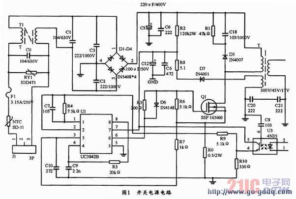
In Figure 1, the T1, C1, C2, and C3 circuits can form an EMI filter to filter the interference of the high-frequency pulse of the power grid to the power supply, and also reduce the electromagnetic interference of the switching power supply itself to the outside world. D1~D4 form a diode bridge rectifier circuit, C5 is a filter capacitor, R3 and C9 are oscillating components of UC342, T is a switching transformer, and Q1 is a switching transistor. When the charger is connected to the power supply, after the circuit is powered, the power supply is rectified and filtered by D1~D4 and C5, and the 310V DC voltage can be output. The 310V voltage is supplied to the 7-pin of the UC3842 via the starting resistor R2, and the C12 is charged when the starting resistor R2 is activated. When the voltage across the capacitor rises, when it rises to more than 16V, the UC3842 turns on and outputs a pulse to push the Q1 field effect transistor into the switching state, the output voltage of the transformer, and the feedback winding is rectified and filtered by D7 and C12 to output 13V~15V. The voltage supplies power to the 7-pin of the UC3842, allowing the UC3842 to enter normal operation to drive the Q1 to work properly. When Q1 enters normal operation, the output winding of the transformer outputs voltage at the same time. Resistor R0 is the sampling resistor. When the load current exceeds the rated value, the field effect current increases. The voltage on R0 is fed back to CSEN (pin 3 of UC3842), and the reset signal is output through the internal current detection comparator, which finally causes the switch to close. . Moreover, it is only possible to turn the switch on again when the next reference pulse arrives. When an output short circuit occurs, the output voltage drops, and the output winding drops for the feedback winding that supplies the UC3842. When the input voltage is lower than 10 V, the UC3842 stops working and stops the trigger pulse output to turn off the FET. When the short circuit disappears, the power is restarted and automatically resumes normal operation. The photocoupler 4N35 and the resistors R4, R9 and R10 form a feedback network, which can feedback the feedback signals of these components to the second leg of the UC3842 through these components to control the on-time of the switch. Thereby achieving the purpose of steady voltage regulation.
3 three-stage charging circuit design
3.1 Design of the first stage constant current source
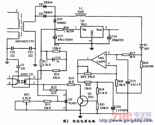
The circuit uses a high-precision operational amplifier LM393 as the core device, and its circuit is shown in Figure 2. When the circuit is energized, a secondary voltage of the transformer is rectified to a positive and negative voltage of the battery to charge the battery. When the current flows through the resistor R34 (resistance resistance is 0.05 Ω), the voltage across the resistor is Ui=IoR. The voltage of Uil is amplified with the voltage comparison amplifier. When it is amplified to turn on the transistor Q2 (the transistor Q2 operates in the critical conduction state), the transistor Q2 will work in the amplification state, thereby lowering the voltage of the two poles of the CE, thereby making the photoelectric coupling. The coupling of the device is strengthened, and the voltage of pin 2 of UC3842 is increased, and the width of the widening pulse is narrowed, so that the conduction time of the field effect transistor is shortened to stabilize the charging current. The magnitude of the charging current can be determined by RP2.
3.2 Design of the second stage constant voltage source
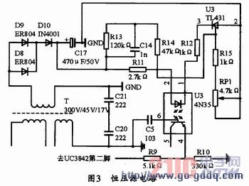
The circuit uses a TL431 precision adjustable reference power supply. The voltage regulation value of TL431 is continuously adjustable from 2.5 to 36V, and its circuit is shown in Figure 3. When the circuit is energized, the transformer secondary in Figure 3 will rectify the output voltage to the battery positive level to charge the battery. This current flows through resistor R11 to power 4N35 and then through TL431 to ground. The voltage across the TL431 is determined by RP1. Adjusting RP1 changes the voltage across the TL431, thereby changing the voltage across the LEDs in the 4N35, thereby controlling the illumination intensity of the LEDs and controlling the feedback. By controlling the output voltage of the 4th pin of 4N35 to the output voltage of the 2nd pin of UC3842, and then adjusting by RP1, the voltage to be output can be obtained.
3.3 Design of the third stage trickle charging circuit
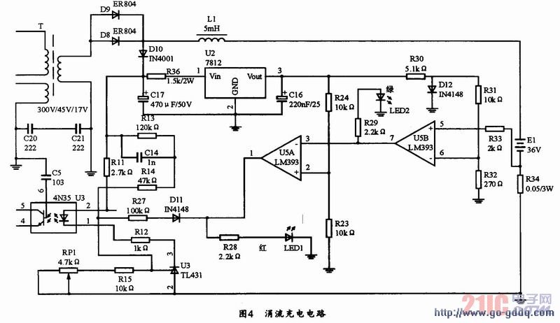
Trickle charging is mainly used to compensate for the capacity loss caused by self-discharge after the battery is fully charged. Generally, it is realized by pulse charging. The circuit is mainly composed of LM393 and TL431. As shown in Figure 4, when the circuit is energized, a secondary rectification output of the transformer is applied to the battery positive and negative stages to charge the battery, and the current flows through the resistor. R34 (resistance resistance is 0.05Ω), the voltage of U5+ and the voltage of U5- will be compared with the voltage across the resistor. When the voltage U5+=IoR>U5-, the circuit outputs a high level, the green light is off and the red light is on. , which means charging is in progress; when the current drops to U5+
3.4 Design of intermittent pulse circuit
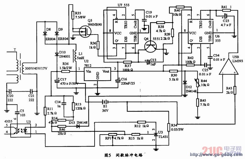
The intermittent pulse circuit is shown in Figure 5. When the circuit is energized, the transformer secondary will rectify the output voltage to the battery positive and negative stages to charge the battery. When the current flows through the resistor R34 (resistance resistance is 0.05Ω), when the voltage across the resistor is V5 (U5B v5) =IoR34) When U5B (5 pin) voltage is higher than 6 pin voltage, 7 pin output is high level, intermittent circuit is on, U6 555 timer starts timing, 3 pin output high level, 5 seconds later timing At the end, the 3 pin outputs a low level. The 3-pin level is clamped by D15, and the potential of pin 1 of TL431 is pulled down by current limiting resistor R46 to reduce the output by 20%. At the same time, U7 is turned on. U7 is also a 555 timer. The timing time is 1 second. The 3 pin of U7 outputs a high level. Controls it to start timing at the same time, and Q3 turns on and discharges. When the timing is over, the 3 pin of U7 outputs a low level, and Q3 turns off the discharge, and sequentially cycles. When the charging current Io drops to a certain level, that is, IoR3
3.5 Design of the heat dissipation circuit
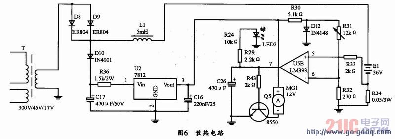
The heat dissipation circuit is composed of 7812, fan motor, integrated operational amplifier LM393 and other devices. The circuit is shown in Figure 6. When the third stage is working, the heat dissipation circuit stops working. The charge current is designed to be 500mA. When the charging current drops to 500ms. When the trickle charge circuit is turned on, that is, when the voltage of the 5 pin of the U5B is lower than the voltage of the 6 pin, the 7 pin outputs a high level, and the 1 pin of the U5A outputs a low level. The clamp diode D11 clamps the voltage of pin 1 of TL431, so that the output drops to 41.3V and trickle charge, the LED green light is on, and the heat dissipation circuit stops working, that is, the fan circuit stops working.
4 Conclusion
The charger is designed by the advantages of three charging methods: intermittent charging, pulse charging, and three-stage charging. The three-stage charging can automatically complete the switching, and has the advantages of fast charging, full charging, low battery loss during charging, and battery repair during charging. At the same time, the intermittent pulse three-stage charger eliminates the problem of high-current charging of other chargers, causing the problem of vulcanization of the battery and the heating of the battery by the large current, and also solves the problems of insufficient battery charging and overcharging of the battery. In short, the intermittent pulse three-stage charger is another major innovation and reform of the charger.
Description for Colorful Sleeves For Wire Cable Harness And Beautification
Expandable braided sleeves is ideal for a limitless number of electronic, automotive, marine and industrial wire management and bundling applications. Examples include engine compartment dress up, home theater wire management, customizing computer case wiring, office wire management, automotive harnesses, scuba hose protection, and many more. Threads of different colors and textures could be braided into different patterns. Each of our products is tailored to the client's business and needs.
PET polyester Expandable Braided Sleeving is flame-retardant and halogen-free. Braided sleeve offers durable abrasion resistance in a wide range of industrial applications. The open weave construction allows an easy installation on a bundle of hoses and cables, even if some with bulky or large connectors.
Totally expanded the sleeving can reach at least one point five times than the initial dimension.
Cable Protection Sleeve,Cable Sleeves Pc,Colorful Braided Sleeve ,Colored Plastic Sleeve
Shenzhen Huiyunhai Tech.Co.,Ltd , https://www.hyhbraidedsleeve.com