Design, working principle of watchdog timer and operation of watchdog timer
The Watchdog Timer (WDT) is an integral part of the microcontroller. It is actually a counter. It usually gives the watchdog a number. After the program starts running, the watchdog starts counting down. If the program is running normally, the CPU should issue an instruction to reset the watchdog and restart the countdown. If the watchdog is reduced to 0, the program is considered to be not working properly, forcing the entire system to reset.
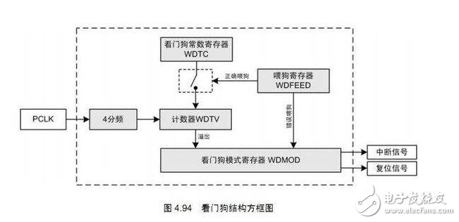
In order to give beginners a systematic concept, first introduce the basic concept of the watchdog. When the embedded system is interrupted by external interference or system errors, the program sometimes “runs awayâ€, causing the entire system to crash. In order to prevent this from happening, a watchdog (WATCHDOG) circuit is often added in situations where system stability is critical. The role of the watchdog is to restore the system's operation when the system "runs away" and enters an infinite loop.
The function of the watchdog timerThe Watchdog Timer (WDT) is an integral part of the microcontroller and has important implications in the debugging and operation of the microcontroller program. Its main function is to reset the microcontroller by resetting the device (if the software does not clear the device) in the event of a software failure. It can also be used to provide a separate protection system for the microcontroller from the sleep or idle mode watchdog timer. In the event of a system failure, the watchdog will respond with a RESET signal after an optional timeout period. For example, the x25045 has an optional timeout period of 1.4 seconds, 600 milliseconds, and 200 milliseconds. When your program crashes, the x25045 resets the microcontroller.
Most watchdog timer ICs generate a single, limited output pulse duration when the watchdog times out. This applies to triggering a reset or interrupting the microprocessor, but some applications require a latch for the output (fault indicator).
In view of safety issues, automotive electronic systems require monitoring circuitry to monitor fault tolerance or safety. The watchdog timer is ideal for this type of demand. It detects the periodic pulses generated by the microcontroller under normal operating conditions, and detects the circuit or? The failure state of C can be immediately switched to the backup/redundant system in the event of a failure. Wake up.
How the watchdog works1. The basic principle is: set the time for the complete running of the system program to be Tp, the timing period of the watchdog is TI, TI "Tp", after the program runs one cycle, the timer value is modified, as long as the program is normal. When running, the timer will not overflow. If the system cannot modify the timer value at Tp due to interference, etc., the timer will overflow at Ti time, causing the system to reset, so that the system can be re-run, thus monitoring. .
2. There is usually a watchdog timer in a complete embedded system or small microcontroller system, and is generally integrated in the processor chip. The watchdog is actually a timer, but it will automatically after expiration. Causes a system reset.
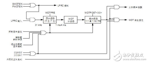
When used, the WDT will increment until it overflows, or "timeout." Unless in Sleep or Idle mode, a WDT time-out will force a device Reset. To avoid a WDT time-out reset, the user must periodically clear the watchdog timer with the PWRSAV or CLRWDT instruction. If the WDT times out in Sleep or Idle mode, the device will wake up and continue executing code from where the PWRSAV instruction was executed. In both cases, the WDTO bit (RCON "4") is set to 1, indicating that the device Reset or wake-up event is due to a WDT time-out. If the WDT wakes up the CPU from Sleep or Idle mode, the “Sleep†status bit (RCON “3â€) or the “Idle†status bit (RCON “2â€) will also be set, indicating that the device was previously in Power Save mode.
A normal WDT time-out will generate a device Reset during normal operation. When the device is in Sleep, a WDT time-out will wake the device to continue normal operation (known as WDT wake-up). Clearing the WDTE setting bit permanently turns off the WDT.
The postscaler assignment is completely software controlled, ie it can be changed at any time during program execution.
To avoid unpredictable device resets, the following sequence of instructions must be executed when changing from the Timer0 prescaler assignment to the WDT postscaler assignment. This sequence of instructions is executed even if the WDT is disabled.
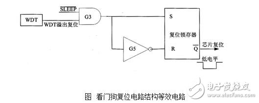
The equivalent circuit diagram of the circuit reset caused by the watchdog WDT is shown in the figure. It can be seen from the figure that only when the status signal SLEEP=1, that is, when the MCU is in a non-sleep state, the watchdog timeout overflow will trigger the reset operation of the MCU. When the MCU is in the sleep state, that is, the status signal SLEEP=0, the watchdog timeout will wake up the MCU.
A watchdog is a counter that counts up pulses provided by an independent clock source without any external components. The independent RC clock source is the external RC oscillator of the RC oscillator and the OSC1 (ULKIIN) pin. The OSC1 and OSC2 external crystal oscillator/ceramic resonators are separated from each other. This means that the watchdog timer WDT will still operate even if the microcontroller enters a sleep state where the system clock is stopped.
During the execution of the program by the microcontroller, a watchdog WDT time-out will cause the microcontroller to generate a reset operation (called a WDT reset). If the microcontroller is in a sleep state, a watchdog WDT time-out will cause the microcontroller to wake up, resume normal operation, and continue executing the program that was put on hold before entering sleep (called WDT wake-up).
Each time the watchdog timeout overflows, the T0 bit in the status register STATUS is cleared to 0 to record the occurrence of this watchdog overflow event for program query judgment.
That is, when WDTE=0, the watchdog WDT will be permanently disabled; when WDTE=1, the watchdog WDT will be permanently enabled. That is to say, as long as WDTE is defined as 1, the operation of the watchdog can no longer be prohibited in the user program.
If you want to prevent the watchdog WDT from overflowing, the watchdog timer can only be cleared continuously and periodically in the user program so that it does not overflow due to the count exceeding the maximum value.
The timing of the watchdog timer depends on the frequency of the independent RC oscillator source and the width of the timer, and is affected to some extent by operating voltage, loop temperature, manufacturing process and other factors.
In addition, the timeout period of the watchdog can also be changed and extended within a certain range by means of the frequency divider and the frequency division ratio of the frequency divider. Whether the divider is configured for use by the watchdog can be set by the PSA bit of the user program definition option register OPTION KEG.
Watchdog design principleIn the watchdog timer, it is a timer circuit. There is usually an input called kicking the dog or service the dog. One output is output to the RST end of the MCU. When the MCU is working normally, every other segment. The time outputs a signal to the feeding dog end, and the WDT is cleared. If the dog is not fed for more than the specified time (usually when the program runs away), the WDT timing is exceeded, and a reset signal is sent to the MCU to reset the MCU. Prevent the MCU from crashing. The role of the watchdog is to prevent the program from infinite loops, or to run the program. In view of real-time monitoring of the operating state of the single-chip microcomputer, a chip dedicated to monitoring the running state of the single-chip microcomputer program, commonly known as a "watchdog" integrated circuit (MAX*9), is generated. A response to the input pulse stream loss is provided to latch the fault indication. The circuit can monitor the fan (the upper fan's speed output calculation), the oscillating circuit, or a microprocessor software to execute.
A simple circuit provides a response to the input pulse stream loss latching fault indication. Based on the μP-supervisor/watchdog integrated circuit (MAX*9), this circuit is used to monitor the fan (calculated at the fan's speed output), the oscillating circuit, or a suitable microprocessor software.
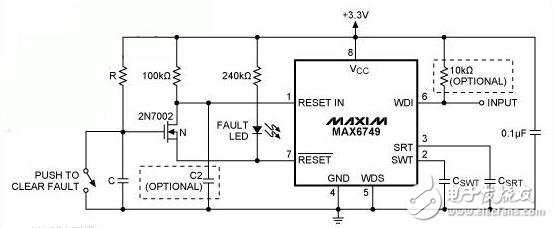
During power-up, the active-low reset is still low until VCC is stable and the reset timeout expires. Capacitor C passes through R until the gate voltage of the FET reaches a threshold (voltage VTH), which turns on the FET to enable latching capability. To prevent false triggering, you should set the RC delay far beyond the reset timeout.
The WDI input (Pin 6) must be set to the lowest rate by the switching capacitor CSWT. If this does not happen, an active low reset goes low, at the LED indicator, at the connection and a low pull reset, thus locking the low reset. The circuit is still active until you cycle VCC or push the switch in this condition. Either turn off the FET's action and allow the reset to go high.
In order to monitor the fan open-drain speed signal, connect 10kΩ from the world development indicator to the VCC (pin 8) pull-up resistor. Since the fan takes some time to spin up, the watchdog circuit needs to be deactivated for a short delay interval. You can reset this delay capacitor (C2) from ground to ground. Note that this delay must be less than the RC delay described above, or the active low reset latch will be too early.
For a fan monitor, set the maximum speed pulse period for the CSWT value according to the formula 5.06 × 10⁶ × CSWT, which CSWT in a few seconds. If the speed is below this threshold, the active low resets the output low and the latch.
Watchdog timer operationA normal WDT time-out will generate a device Reset during normal operation. If the device is in Sleep, a WDT time-out will wake the device and continue normal operation (known as WDT wake-up). Clearing the WDTE setting bit permanently turns off the WDT.
The postscaler assignment is completely software controlled, ie it can be changed at any time during program execution.
To avoid unpredictable device resets, the following sequence of instructions must be executed when changing from the Timer0 prescaler assignment to the WDT postscaler assignment. This sequence of instructions is executed even if the WDT is disabled.
The figure shows the functional block diagram of the watchdog timer.
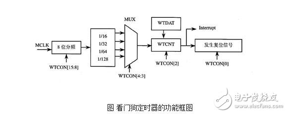
The S3C44B0X watchdog timing uses MCLK as the clock source, and the desired frequency is obtained after 8-bit prescaler and 4-bit split 2-bit division. The prescaler value and the frequency split value are configured in the watchdog timer control register WTCON. The valid prescaler value ranges from 0 to 28-1, and the frequency split factor can be selected from 16, 32, 64 or 128. Use the following formula to calculate the watchdog timing frequency and each timer clock period value.
Twatchdog=1/MCLK/(prescaler value +1)/divide factor
When the watchdog timer is enabled, WTDAT (Watchdog Timer Data Register) cannot be automatically loaded into WTCNT (Watchdog Timer Count Register). Therefore, the initial value must be written to the watchdog timer count register WTCNT before the watchdog timer starts operating.
Main Marine Diesel Generator,Off Shore Diesel Generator,Platform Marine Generator,Marine Propulsion Engine
Jiangsu Vantek Power Machinery Co., Ltd , https://www.vantekpower.com