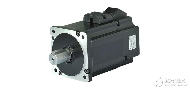
The function of the DC servo motor speed control unit is to convert the speed command signal into the voltage value of the armature to achieve the purpose of speed adjustment. Modern DC motor speed control units often use thyristor (SCR) speed control system and transistor pulse width modulation (PWM) speed control system.
The concept of speed regulation has two aspects:
(1) Change the motor speed: When the command speed changes, the speed of the motor changes accordingly, and it is hoped to reach the new command speed value with the fastest acceleration and deceleration;
(2) When the command speed does not change, the speed of the motor remains stable.
In order to adjust the motor speed and direction, it is necessary to control the magnitude and direction of the DC voltage. How to control it?
The role of the DC servo motor speed control unit: converts the speed command signal into the voltage value of the armature to achieve the purpose of speed adjustment.
The speed control method commonly used by the DC motor speed control unit: thyristor (thyristor) speed control system; transistor pulse width modulation (PWM) speed control system.
1, thyristor speed control systemWhen the AC power supply voltage is constant, when the control voltage Un* is changed, the armature voltage Ud of the DC motor is changed by the control circuit and the thyristor main circuit to obtain the motor rotation speed required by the control voltage Un*. The actual voltage Un of the motor is compared with Un* as feedback to form a speed loop for the purpose of improving the mechanical characteristics of the motor during operation.
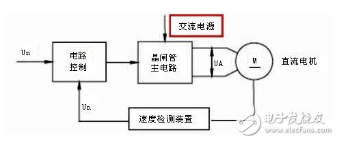
The main circuit of the thyristor speed control system uses a high-power thyristor. The role of high power thyristors:
(1) Rectification. Turning the AC power of the grid into DC; amplifying the control power of the regulation loop to obtain a higher voltage and a larger current to drive the motor.
(2) Inverter. In the reversible control circuit, when the motor brakes, the inertia energy of the motor operation is converted into electric energy, and is fed back to the AC grid to realize the inverter.
In order to control the thyristors, a trigger pulse generator must be provided to generate the appropriate trigger pulses. The pulse must be synchronized with the frequency and phase of the power supply to ensure proper triggering of the thyristor
The main circuit consists of a three-phase full-control bridge type anti-parallel reversible circuit composed of high-power thyristors. It is divided into two parts (I and II). Each part is connected by three-phase bridge type, and the two sets are reversed and connected to realize forward rotation. And reverse.
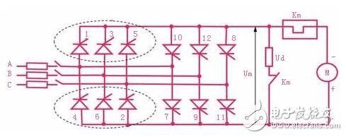
Each of the thyristors is simultaneously turned on to form a loop. In order to ensure that the two thyristors connected in series can be turned on at the same time after the switch-on or the current is turned off, a trigger pulse must be simultaneously issued for one thyristor of the common anode group and one thyristor of the common cathode group.
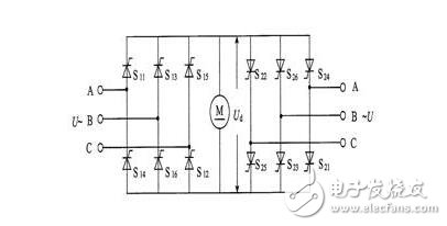
The thyristor speed control system uses a high-power thyristor, which has two functions. One is used for rectification, which turns the AC power supply of the power grid into DC; the other is the inertia of the motor running when the motor brakes in the reversible control circuit. It can be converted into electrical energy and fed back to the AC grid to achieve inverter. In order to control the thyristors, a trigger pulse generator must be provided to generate the appropriate trigger pulses. There are many types of rectifier circuits for thyristors. The most commonly used three-phase bridge type anti-parallel reversible circuits in CNC machine tools.
As shown in the figure is a three-phase bridge type anti-parallel reversible circuit. It consists of 12 thyristor high-power thyristors. The thyristors are divided into two groups, S11 to S16 are a group, and S21 to S26 are a group. Each group is connected by three-phase bridge type, and the two groups are anti-parallel to realize forward rotation and reverse rotation respectively. Anti-parallel means that the two sets of converter bridges are connected in parallel with reverse polarity and are powered by an AC power supply. Each group of thyristors has two operating states: rectification and inverter. One group is in rectification work and the other group is in inverter state. The inverter group works when the motor is decelerating.
The voltage waveform of the three-phase fully controlled bridge circuit is shown in the figure. The thyristor firing angle α indicated on the graph is π/3. The thyristors are turned on in order at intervals of π/3, and every six pulses of the motor are rotated by one revolution. Since the thyristor is triggered at a faster rate, the current flowing through the motor is almost continuous.
The working process is as follows: When ωt=π/6+α, S11 is turned on and S16 has been turned on before then. Therefore, when the A-phase voltage waveform is in the interval of π/6+α<ωt<π/6+α+π/3, the thyristors S11 and S16 are turned on, and the motor terminals are connected to the A phase and the B phase, so Ud=UAB . When ωt = α + π / 3 + π / 6, the thyristor S12 is turned on, current flows through S12, and S16 is turned off due to reverse bias (natural or grid commutation). At this time, S11 and S12 are turned on, and the voltage across the motor is Ud=UAC. In this way, a thyristor is turned on every π/3, and the above process is repeated.
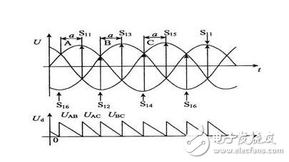
It can be seen from the waveform diagram that as long as the value of the firing angle α is changed, the input value of the motor voltage can be changed, thereby adjusting the current value of the armature of the DC motor to achieve the purpose of adjusting the speed of the DC motor.
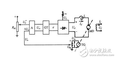
In the figure, RW1 is the speed positioner U+n, which is the speed deviation voltage, Un is the speed feedback voltage, ΔUn is the feedback deviation voltage, A is the proportional amplifier, Uct is the trigger control voltage, and GT is the trigger control device of the thyristor.
The working condition of the system and the automatic speed regulation process are as follows:
When the system starts under a certain given speed U+n, the motor does not rotate for a moment, so the speed feedback voltage Un=0, the feedback deviation voltage ΔUn=U+n, after passing through the amplifier, the output For larger Uct, the trigger angle α of the trigger output will decrease from 90o in the initial state, and the output voltage of the rectifier will also rise from Ud=0 to a certain larger value. The motor is under this voltage (the current does not exceed the allowable When the value is), the operation starts. As the rotational speed increases and the feedback voltage Un rises, the rotational speed deviation voltage ΔUn decreases, Uct decreases, α increases, the rectifier output voltage Ud also decreases, and the motor slip rate also decreases until the rotational speed n approaches a given rotational speed, ie, feedback When the voltage Un is close, the motor runs smoothly. As mentioned earlier, the motor speed can only be close to a given speed, and the magnitude of the deviation is closely related to the magnification. However, this kind of system is biased in principle, so it is called a differential speed control system.
Thyristor power supply speed current double closed loop DC speed regulation system
The above-mentioned speed negative feedback single closed-loop speed control system can not be used in the CNC machine feed system. For the high speed control system on the CNC machine, it requires fast start and brake, and the dynamic speed drop should be small. A speed double current closed loop system is usually used.
The speed and current double closed loop speed control system is shown in the figure. In order to realize the two feedbacks of speed and current respectively, two regulators are set in the system to adjust the speed and current respectively, and a cascade connection is implemented between the two.
(1) Principle: Using the switching action of a high-power transistor, the DC voltage is converted into a square wave voltage of a certain frequency and applied to the armature of the DC motor; the average voltage of the armature is changed by adjusting the square wave pulse width, thereby Adjust the speed of the motor.
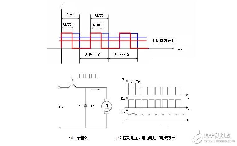
Average value of DC motor voltage

Where T is the pulse period and Ton is the on time
Features: The control circuit is simple, no additional shutdown circuit is required, and the switching characteristics are good. Widely used medium and small power DC servo system.
(2) The composition of the PWM system
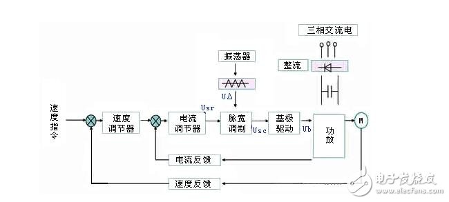
USr - the DC voltage converted from the speed command;
U△——triangular wave;
USC - the output of the pulse width modulator (USr + U â–³);
Ub—The pulsed output of the modulator output, the pulse voltage converted by the base drive.
Control loop: speed regulator, current regulator, fixed frequency oscillator and triangle wave generator, pulse width modulator and base drive circuit.
Difference: Compared with the thyristor speed control system, the speed regulator and the current regulator have the same principle. The difference is the pulse width modulator and power amplifier.
PWM system pulse width modulator
Function: Convert the voltage amount into a rectangular pulse that can be adjusted by the control signal, and provide a pulse width voltage whose width can be adjusted by the speed command signal for the base of the power transistor.
Composition: Modulation signal generator (triangular wave and sawtooth wave) and comparison amplifier.
Transistor speed control system main circuit
The switching power amplifier is the main loop of the pulse width modulation speed unit. There are two types of structure, one is H type (also called bridge type), and the other is T type. Each circuit has a unipolar mode of operation and a bipolar mode of operation, and various different modes of operation can form a reversible switch amplifying circuit and a non-reversible switching amplifying circuit.
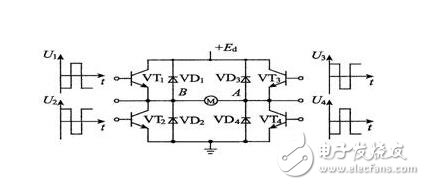
The diagram shows the working principle of a widely used H-type switching circuit, which is a bridge circuit consisting of four diodes and four power tubes. The DC power supply +Ed is powered by three sets of full-wave rectified power supplies. The pulse waves u1, u2, u3, and u4 outputted by the pulse width modulator are converted into pulse signals U1, U2, U3, and U4 having the same phase and polarity as each pulse via an optical isolator, and are applied to the switching power tube VT1. ~ VT4 base. When the motor works normally, in the time interval of 0 "t", U2 and U3 are high level, and the power transistors VT2 and VT3 are turned on. At this time, the power supply and +Ed are added to the two ends of the armature to supply power to the motor. The current direction is from the power supply +Ed via VT3 → motor → VT2 → back to the power supply. In t1 ≤ t "t2 period U1, U3 are low level, VT1 and VT3 are off, +Ed is cut off. At this time, U2 is still at a high level. At this time, due to the action of the armature inductance, the current continues to flow through VT2 and the freewheeling diode VD4. When t2 ≤ t "t3, U2 and U3 are positive at the same time, and +Ed is added to both ends of the motor via VT2 and VT3, and the current continues to flow. When t3 ≤ t "T, U2 and U4 are both negative at the same time, the power supply is cut off again, and U3 is positive, so the armature current continues to flow through VT3 and VD1, so that the cycle is repeated. The voltage UAB obtained by the main circuit is a pulse voltage that varies between +Ed and O.
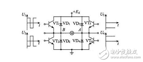
The bipolar and unipolar circuit schematics are identical, except that the drive signals are different for the two tubes on the right.
Pulse Width ModulaTIon (PWM) speed control system
(1) Working principle of DC PWM servo drive
The PWM driver is a DC power source that modulates a fixed voltage by utilizing the switching characteristics of a high-power transistor, turns on and off at a fixed frequency, and changes the length of the on and off times in one cycle as needed, by changing the DC. The "duty cycle" of the voltage on the armature of the servo motor changes the magnitude of the average voltage to control the speed of the motor.
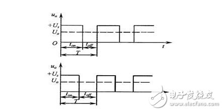
The schematic diagram of the PWM control is as shown in the figure. The controllable switch S is repeatedly turned on and off at a certain time interval. When S is turned on, the power supply U is applied to both ends of the motor through the switch S, and the power supply supplies energy to the motor. The motor stores energy; when the switch S is opened, the energy supply to the motor is interrupted. The energy stored by the armature inductance during the opening of the switch S causes the motor current to continue to flow through the freewheeling diode VD.
If the voltage waveform is shown at the ends of the motor, the average voltage obtained by the motor is:
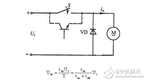
It is known that changing the ton and toff can change the speed, but this must be done with the corresponding device. The diagram shows a block diagram of a PWM driver system.
It is known from the figure that the control structure of the PWM driving device can be divided into two parts: a power conversion circuit that transfers energy from the main power source to the motor and a control circuit. The power conversion circuit can be an H-type and a T-type power amplifying circuit; the control circuit is usually composed of a basic circuit such as a constant frequency waveform generator, a pulse width modulation circuit, a base driving circuit, and a protection circuit.
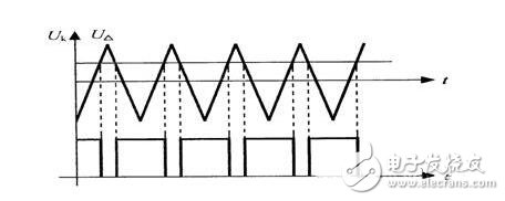
When the triangular wave voltage UΔ and the DC voltage Uk are sent to the amplifier, if the triangular wave is higher than the control voltage, the output is “emptyâ€; otherwise, the output is “occupiedâ€, and the duty ratio can be changed by changing the control voltage Uk. Its output waveform is shown in the figure.
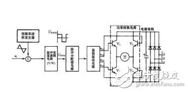
The pulse distribution circuit performs appropriate logic transformation on the V/W converted signal according to the power conversion circuit working mode, and distributes it to the base driving circuit to meet the voltage requirement of the on/off timing pulse when the power conversion circuit operates.
In the all-digital DC speed regulation system, only the input signal and the output signal of the power conversion component and the execution component are analog signals, and the remaining signals are digital signals, which are implemented by a computer through an algorithm.
The calculation speed of the computer is very high. The input and output values ​​of the current loop and the speed loop can be calculated within a few milliseconds, and the data of the control square wave is generated, thereby controlling the rotational speed and torque of the motor. The all-digital speed regulation is characterized by discretization, that is, the control data is given once per sampling period.
In one sampling period, the computer completes the calculation and output of the control data of the current loop and the speed loop, and controls the speed and torque of the motor once.
According to the type of sensor, the Touch Screen is roughly divided into infrared type, resistance type, surface acoustic wave type and capacitive touch screen four kinds. The design of capacitive touch screen is reasonable, but the problem of image distortion is difficult to be solved.
Capacitive touch screen
The touch screen works by using the body's current induction process. A special transparent metal conductive substance is coated on the surface of the glass. When a conductive object touches the glass, it changes the capacitance of the contact, so as to detect the position of the touch. But touching a non-conductive object with a gloved hand or hand does not respond because of the addition of a more insulating medium.
Capacitive touch screen can sense light and fast touch, anti-scratch, not afraid of dust, water and dirt influence, suitable for harsh environment. However, capacitance varies with temperature, humidity or environmental electric field, so its stability is poor, low resolution and easy to drift.
Capacitive Screen,Projected Capacitive,Capacitive Touch Panel,Projected Capacitive Touch
Tonya Display Limited , https://www.tydisplay.com