Ruifeng Optoelectronic Technology Development Office: Dong Chunhui, Xiao Ming, Chen Hua, Cai Jie
Briefly introduce LCD TV and color filter (CF) and white LED that affect color gamut coverage, and explain the conversion relationship between CF and white LED in LCD, and the calculation method of color gamut coverage. A phosphor scheme for backlighting white LEDs with different color gamut coverage is briefly described with examples.
1 Introduction
Due to its high color performance, high light efficiency, low carbon environmental protection and energy saving, a large number of LCD TVs on the market are beginning to use LEDs as backlights. However, due to the variability of LED white light synthesis, many packagers' technicians are not well aware of how to choose a phosphor solution that matches the LCD under the known color gamut coverage requirements. At the same time, due to the different LCDs of various TV manufacturers, the technicians of the package manufacturers need to perform multiple and long-term package verification on the phosphor solution that meets the requirements of color gamut coverage and matches the LCD. This paper mainly explains and analyzes the conversion relationship between CF and white LED in LCD, the calculation method of color gamut coverage and how to choose the phosphor matching with CF in LCD under the requirement of known color gamut coverage. For reference by the packaging technician.
2 LCD TV and color gamut coverage
2.1 LCD TV Introduction
LCD: Abbreviation for Liquid Crystal Display, the full name of liquid crystal display, which includes TFT, UFB, TFD, STN and other types of liquid crystal display.
Liquid crystal: a substance between a solid and a liquid. It is an organic compound with a regular molecular arrangement. If it is heated, it will be in a transparent liquid state. If it is cooled, crystal particles will appear. Turbid solid state. Because of its characteristics, it is called liquid crystal. The liquid crystal molecular structure used for the liquid crystal display is similar to that of a fine match stick, and is called a Nematic liquid crystal. A liquid crystal display made of such a liquid crystal is also called an LCD.
LCD TV: A TV set that uses a liquid crystal display to make a display.
2.2 LCD construction and imaging principles
2.2.1 LCD construction
Taking a TFT type liquid crystal display as an example, the structure mainly includes a backlight, a light guide plate, an upper and lower polarizing plate, a liquid crystal, a color filter, a thin film transistor, etc. (the structure is shown in FIG. 1), and the main structural functions are as follows:
1. Back Light: The principle of LCD display is to block the light and light by the liquid crystal to control the light and dark. It is necessary to have a light source to see the image on the screen, so the backlight is responsible for providing the most basic for LCD display. Light source.
2. Light Guide Plate: distributes the light evenly across the entire screen;
3. Up/Down Polarizer: The direction of the light sent by the backlight is inconsistent and radial. If such light passes through the twist of the liquid crystal molecules, we still can't see the image we want to see on the screen. At this time, the polarizing plate below assumes the work of normalizing the direction of the light to the liquid crystal layer.
4. Thin Film Transistor (TFT): Controls the twist angle of liquid crystal molecules
5. Liquid crystal: This layer of liquid crystal molecules is twisted under the control of the TFT, and the light with the same direction is controlled to be bright, so that the brightness of the light to the rear pixel unit changes.
6. Color Filter: After the white filter is filtered, we can see that the light corresponding to the color of the filter is transmitted, so in the LCD screen, the function of the color filter is to color. .
.jpg)
2.2.2 LCD imaging principle
The principle of LCD imaging is to place the liquid crystal between two sheets of conductive glass. By controlling the driving of the electric field between the upper and lower polarizing plates and the upper and lower electrodes, the electric field effect of the liquid crystal molecules is twisted and nematic to control the transmission of the backlight or Masking, combined with other control and auxiliary function layers to achieve the function of restoring the picture.
2.2.3 LCD TV backlight introduction
Since the liquid crystal must be illuminated by an additional light source, the backlights commonly used in LCD TVs include CCFL (Cold Cathode Fluorescent Lamp, which is our common fluorescent lamp), LED (Light Emitting Diode), and HCFL (Hot Cathode Fluorescent Lamp). Among them, CCFL is currently the most commonly used LCD backlight, usually called traditional backlight;
CCFL vs. LED:
CCFL - made of hard glass and trichromatic phosphors, the tube has a proper amount of mercury and inert gas, the inner wall of the tube is coated with phosphor, and there is one electrode at each end. The disadvantage is that the color displayed is limited. .
LED - is a semiconductor solid-state light-emitting device that uses a solid semiconductor chip as a light-emitting material to recombine excess energy in a semiconductor by carrier to cause photon emission, directly emitting red, yellow, blue, green, cyan, and orange. , purple, white light. Because LED LEDs have good color performance, they have completely replaced the light source of traditional cold cathode fluorescent tubes.
2.3 gamut coverage
2.3.1 Meaning of gamut coverage
Color Gamut: refers to the range of the number of colors that a display system can express.
In order to be able to visually represent the concept of color gamut, the CIE International Lighting Association has developed a method for describing the color gamut: the CIE-xy chromaticity diagram. In this coordinate system, the gamut range that each display system can represent is represented by a triangular area composed of RGB three-point lines. The larger the area of ​​the triangle, the larger the gamut range of such a display device.
Color gamut coverage: The horseshoe-shaped chromaticity triangle marked with color on the CIE-xy chromaticity diagram is the color area that the human eye can see. If a system can fully reproduce the color in this horseshoe-shaped area, it can be said to be color. The domain coverage is 100%. The triangular regions composed of the three primary color coordinates of R, G, and B when the colors are reproduced by R, G, and B are the color reproduction regions determined by the three primary colors, and the ratio of this region to the horseshoe region is the color gamut coverage. Therefore, the gamut coverage ratio is the ratio of the area of ​​the triangular area composed of three basic color coordinates of R, G, and B to the area of ​​the triangular area composed of the three primary color coordinates of the standard R, G, and B.
2.3.2 Standards for gamut coverage
Traditionally, we refer to gamut coverage as the color gamut. In different fields, the requirements for the three primary color coordinates of the standard R, G, and B are different, which involves different color gamut evaluation criteria. The gamut standards generally have the following:
1) NTSC Standard: In 1953, the National Television Standards Committee (NTSC) developed the NTSC standard based on the CIE1931 chromaticity diagram, which is also a commonly used standard in China.
2) ITU-R BT.709 standard: A standard established by the International Radio Consultative Committee (CCIR) in 1988 for television production in high definition television (HDTV) studios.
3) sRGB standard: In 1996, the gamut standard for digital image developed by the International Electrotechnical Commission (IEC), which is mainly applied to digital image acquisition equipment, is not widely available on the display.
4) Adobe RGB standard: In 1998, Adobe proposed a color space wider than sRGB, which is generally used in printing and publishing, image processing and other fields.
5) ITU-R BT.1361 standard: Wide color gamut standard based on Pointer color gamut established by the International Telecommunication Union Radiocommunication Group (ITU-R) in 1988.
6) xvYCC standard: The latest generation of optical gamut standard approved by the International Electrotechnical Commission (IEC) and published as an international standard in January 2006. Its color range not only greatly exceeds the NTSC gamut range, but also reaches the sRGB color gamut. Times, this specification can define all colors visible to the naked eye.
The common standards in the above gamut standards are: sRGB, NTSC and Adobe RGB. The coordinates of the white light position, color temperature and RGB primary color are shown in Table 1:
.jpg)
In this paper, the color gamut we are talking about is the color gamut under the NTSC standard, referred to as the NTSC color gamut.
Combined with the concept of color gamut coverage, it can be deduced that the NTSC color gamut is the ratio of the triangle region composed of a certain RGB three primary color coordinates to the triangular region composed of three color coordinates of NTSC standard RGB (schematic diagram is shown in Figure 2). The higher the ratio, the color The better the performance.
.jpg)
The development of backlights from CCFL to LEDs indicates that people are increasingly demanding the range of colors that can be expressed by the system, so the future high color gamut will become the trend of LCD TV development.
2.4 Factors affecting gamut coverage
Combined with the structure and imaging principle of the LCD in 2.2, it can be known that in the LCD TV, the light of the backlight passes through the CF to obtain the light of the three primary colors of RGB. At the same time, the content of 2.3 is known that the NTSC color gamut is the ratio of the triangle region composed of a certain RGB three primary color coordinates to the triangular region composed of three color coordinates of NTSC standard RGB. Therefore, the key factors affecting the gamut coverage are the three color coordinates of the backlight (mainly white LED), CF, and standard RGB. Under the NTSC standard, the standard RGB three color coordinates are known.
2.4. Introduction of 1 white LED
The white LED is a device packaged by chips, brackets, phosphors, glues, etc., and its luminescence spectrum can be visually described by a continuous RGB curve. In practical applications, white LEDs generally have the following two implementations:
1) Blu-ray chip (B) + yellow phosphor (Y);
2) blue chip (B) + green phosphor (G) + red phosphor (R);
2.4.2 Introduction to CF
Structure of CF
It is known in the article 2.2.1 that white light passes through the filter in the LCD (the position in the LCD is shown in Figure 1), and the light corresponding to the color of the filter will be transmitted, indicating that CF has the ability to separate a certain white light into R, G, B three-color light function.
CF is actually composed of three kinds of filters: R, G, and B (the plan is shown in Figure 3 and the cross-sectional view is shown in Figure 4). Only the light with the spectrum of the filter can penetrate the filter better. After the spectrum passes through the R, G, and B filters of CF, a new spectrum is obtained (this transformation is shown in Figure 5). The spectrum is decomposed by R, G, and B to obtain three independent R, G, and B. spectrum.
.jpg)
.jpg)
LED white light passes through CF to get another new white light spectrum. This new white light is actually composed of three independent R, G, and B spectra. The detailed process is as follows: .jpg)
CF theory analysis
1. The characteristics of a CF model can be represented by a curve image (Fig. 7). The curve is actually composed of three single curves of R, G, and B (Fig. 8). The meaning of each curve can be simple. The understanding is as follows:
Curve - the peak is around 650nm, the band distribution is 570-780nm, which means that the light in the 570-780nm band can pass, and the other bands will be filtered out. At the same time, in the 570-780nm band that can pass, and because of the wavelength The difference in energy intensity that leads to the difference is also different.
Curve - the peak is around 530nm, the band distribution is 465-615nm, which means that the light in the 465-615nm band can pass, and the other bands will be filtered out;
Curve - the peak is around 460nm, the band distribution is 400-520nm, which means that the light in the 400-520nm band can pass, and the other bands will be filtered out;
.jpg)
2. There are differences between different manufacturers and different types of CF. Now compare the curves of R, G and B with two common CFs in China. .jpg)
According to the analysis, the peak and half-wave widths of the R, G, and B curves in the two CFs of A and B are as follows:
Table 2: Peak and half-wave widths of the R, G, and B curves in the two CFs A and B
.jpg)
The above data shows that although the R, G, and B parameters of the two types of CF are roughly the same, the details still differ, so in the application, the specific CF model needs to be determined to determine the matching scheme.
2.5 Calculation of gamut coverage
Description: According to the introduction of 2.4.2 CF, LED white light will get 3 single R, G, B spectra after CF, and then the three single R, G, B spectra will be mixed into white light after CF. .
.jpg)
3 color gamut coverage and selection of phosphor scheme
3.1 Characteristics of different system phosphors
The peak wavelength and half-wave width are distinguished. The characteristics of LED phosphors of different systems can be summarized as follows:
.jpg)
Table 3 Peak wavelength and half-wave width parameters of LED phosphors of each system
3.2 Color gamut coverage and selection of phosphor scheme
Analysis 1. From the theoretical analysis of 2.4.2 CF, the peak of the R curve in the two CFs commonly used in China is about 650 nm, the half-wave width is >100 nm, the peak of the G curve is about 530 nm, and the half-wave width is about 100 nm. The peak value of the curve is between 460-475 nm and the half-wave width is 90 nm. This indicates that in order to match the corresponding CF, the peak wavelength and half-wave width of the powder should be paid attention to when selecting the phosphor scheme.
Analysis 2, because the phosphor is encapsulated into LED white light, it is a continuous waveform composed of RGB (Fig. 11). In order to make white light better match CF, three narrower half-width R, G, B waveforms are needed. (Figure 12). When the half-width of the phosphor is narrower, the whole spectrum tends to the spectrum of monochromatic light. At this time, the color purity of the phosphor is higher, and the white light spectrum mixed by such phosphor is closer to the ideal. White light spectrum (Fig. 13), such white light passes through CF, and the color gamut coverage is high.
.jpg)
.jpg)
Analysis 3, from the meaning of color gamut coverage, the color gamut coverage is the area of ​​the triangle area composed of three basic color coordinates of R, G, B and the triangular area of ​​the standard R, G, B three primary color coordinates. The ratio, which indicates that the coordinates (x, y) of the phosphor should be also considered when selecting the phosphor scheme.
Based on the analysis of the above three points, the realization of white light, and Table 3.1-1, it can be seen that in the selection of the phosphor scheme, Ga powder can be selected from Ga-YAG, LuAG, Silicate, β-SiAlON, and quantum dots, and R powder can be selected from Nitride. KSF, quantum dots. At the same time, in order to achieve the best color gamut coverage, you can choose a narrower half-width phosphor to match.
For example: G powder of β-SiAlON + R powder of quantum dots, G powder of quantum dots + R powder.
3.3 Case description of different color gamut coverage requirements and phosphor schemes
Combined with the existing materials and LED packaging experiments in the industry, the phosphors required for different color gamut coverage (70%, 75%, 80%, 85%, 90%, 95%) of the NTSC standard under the A model CF model are sequentially illustrated. The matching scheme, its parameters and the LED white light spectrum after encapsulation are as follows:
Table 4 Phosphor parameters of different color gamut coverage requirements of NTSC standard under A .jpg)
Note: The above simply enumerates some of the phosphor program parameters that meet the NTSC standard color gamut coverage requirements.
.jpg)
.jpg)
5 Conclusion
This paper briefly introduces LCD TV and CF and white LED which affect the gamut coverage. It also explains the conversion relationship between CF and white LED in LCD and the calculation method of color gamut coverage. At the same time, it covers different color gamut with examples. A brief introduction to the phosphor scheme for backlighting white LEDs is given.
references
[1] Tang Shunqing. Colorimetry [M], Beijing: Beijing Institute of Technology Press, 1990, 06
[2] National Radio and Television Product Quality Supervision and Inspection Center, TPC Multimedia Technology Co., Ltd. GPC R&D Center. Colorimetry in Digital TV and Flat Panel TV [M], Beijing: People's Posts and Telecommunications Press, 2010.2, 36-55
[3](US)William.K.Pratt] Digital image processing production method, digital image processing production process digital image processing processing method, [M], Beijing: Mechanical Industry Press, 2010.3, 36-55

The Touch Monitor is a product developed and designed by ourselves. It has been sold for more than 6 years and has exceeded 160,000 units. At present, it is running very well. It mainly customizes different touch technologies, different sizes, different interfaces, connecting cables and power supply parts to meet the needs of guests. We provide customers with the choice of Resistive Touch Screen, Capacitive Touch Screen, Infrared Touch Screen and nano touch foil, and customize various interfaces for customers, such as: VGA, DVI, HDMI, DP and so on. It is mainly used in banks, hospitals, government units, airports, railway stations, supermarkets, real estate and other places.
Product show:

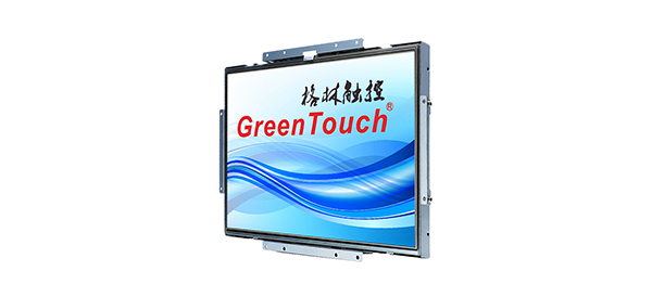
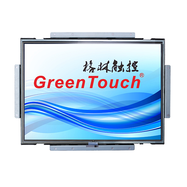
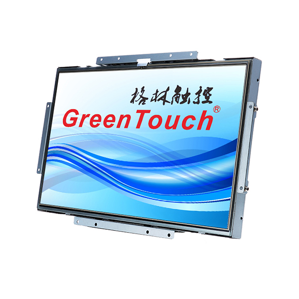
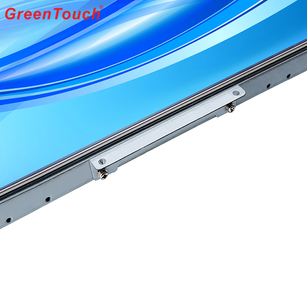
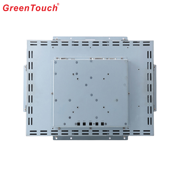
Touch Monitor
Touch Screen Monitor,Multi Touch Display Monitor,Outdoor Touch Screen Monitor,Waterproof Touch Monitor,Commercial Touch Screen Monitor,KTV Touch Screen Monitor
ShenZhen GreenTouch Technology Co.,Ltd , https://www.bbstouch.com