As the demand for LED (light-emitting diode) luminaires continues to grow, new thermal technologies enable manufacturers to produce LEDs with higher light output and longer lifetimes. LEDs offer many advantages, including low power consumption, long life (light bulbs can be used for up to 40,000 hours or more) and environmentally friendly (no mercury). As new manufacturing technologies reduce LED production costs and enhance their heat dissipation capabilities, LED shortcomings (such as higher prices than incandescent or fluorescent) will gradually disappear.
According to information provided by the US Department of Energy's Office of Energy Efficiency and Renewable Energy, heat dissipation is one of the most important factors in the successful design of LED systems. Light-emitting diodes can only convert 20% to 30% of electrical energy into visible light, and the rest are converted into heat, which must be imported into the board and heat sink from the LED chip . Excess heat reduces the light output of the LED and shortens its life. Therefore, the improvement in heat dissipation efficiency is very important to optimize the performance potential of LEDs.
Replace with heat sink
Currently, LED substrates or modules for high power/high brightness applications are soldered to a metal based printed circuit board (MCPCB), reinforced heat printed circuit board or ceramic substrate, and the substrate is then bonded to the heat sink. Although this configuration is widely used in the LED industry, it is not the best way to dissipate heat, and the manufacturing cost can be high.
MCPCBs and reinforced thermal printed circuit boards have good thermal performance, but design flexibility is limited, and if heat dissipation is required, the cost can be high because of the additional cost of venting and costly thermal insulation. The ceramic substrate may be made of a ceramic having a low thermal conductivity but being inexpensive (such as an alumina ceramic), or a ceramic having a high thermal conductivity but being very expensive (such as an aluminum nitride ceramic). In summary, the cost of ceramic substrates is higher than that of MCPCBs and reinforced heat-dissipating printed circuit board substrates.
In order to replace the above substrate, LED manufacturers are testing a method of fabricating a circuit directly on an aluminum substrate because this method can provide excellent thermal conductivity. Due to its advantages, the LED industry is interested in using aluminum, but the LED circuit on the aluminum substrate requires an insulating layer. Now, advances in thick film technology have enabled the LED industry to gain the benefits of using aluminum substrates.
The thick film thermal insulation slurry supplier Heraeus Material Technology's material system for aluminum substrates (IAMS) is a low-temperature sintering (less than 600 ° C) thick film insulation system that can be printed and sintered on aluminum substrates. The IAMS material system comprises a dielectric paste, a silver conductive paste, a glass protective layer, and a resistive paste. These materials are suitable for 3000, 4000, 5000 and 6000 series aluminum substrates.
Advantages of IAMS
Mr. Kondo, the global LED project manager of Heraeus's thick film materials division, said: "IAMS is an insulation system designed for aluminum substrates. Aluminum can't withstand temperatures above 660 degrees Celsius. Standard thick film products are based on ceramics and must be at high temperatures. Sintering, the temperature is as high as 800 degrees Celsius to 900 degrees Celsius.
PCB Connectors: Backplane, Wire-to-Board, Board-to-Board Connectors
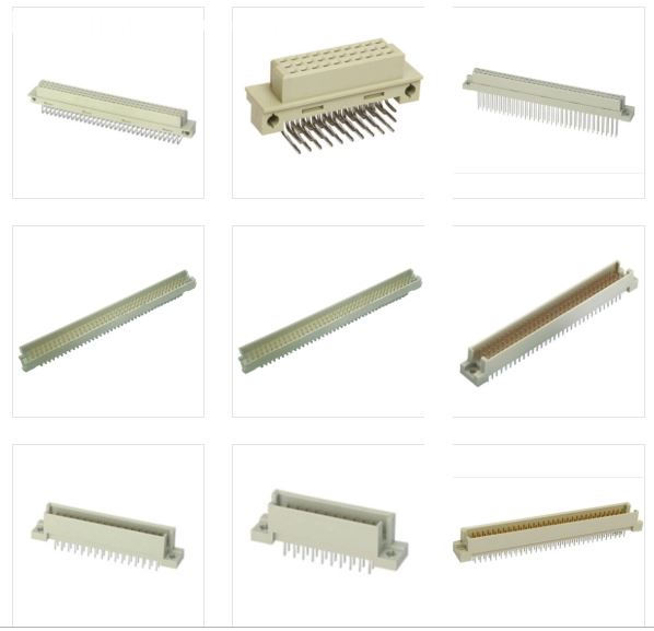
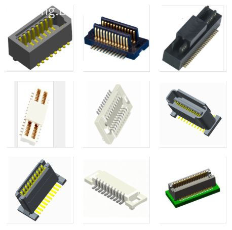
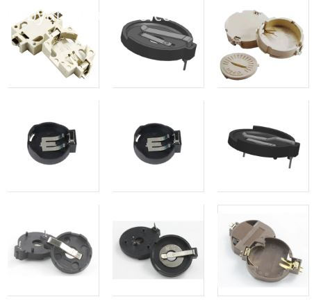
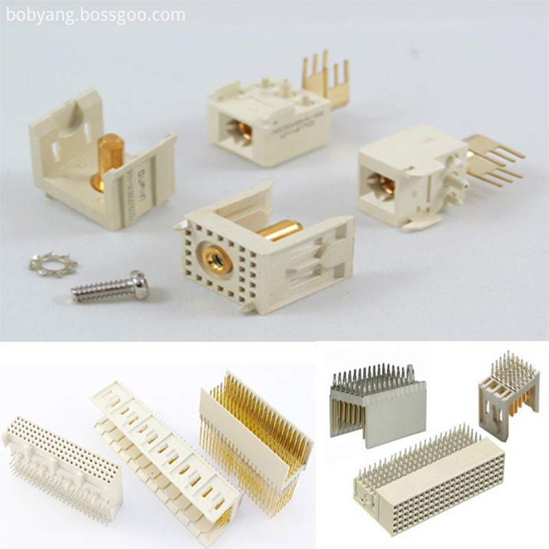
These types of connector systems are mounted or processed to a printed circuit board (PCB). There are a variety of PCB Connectors and accessories best designed for specific uses. To name some, they include: Din41612 Connector ,Board To Board Connectors,Battery Holders Clips Contacts,Future Bus Connectors, PLCC Connectors .
Din41612 Connector
Board To Board Connectors
Battery Holders Clips Contacts
Future Bus Connectors
PLCC Connectors
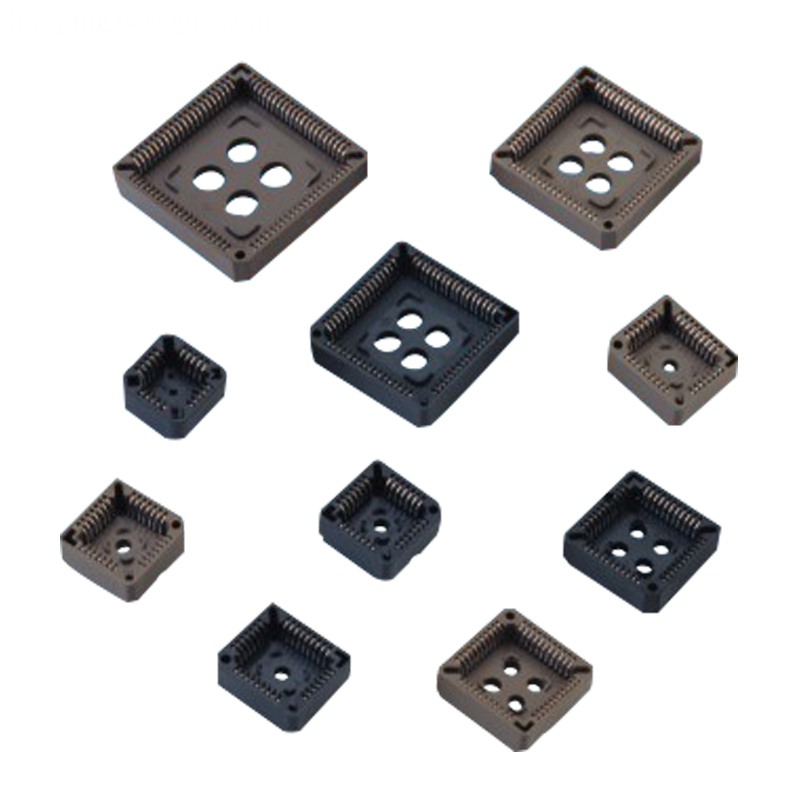
1.ANTENK manufactures a wide range of application specific board stacking PCB connectors which were designed and built to specific customer requirements. Our experienced staff has developed custom products in a variety of contact styles, pitches and stacking heights. Our designs range from new concepts to duplicating existing market products identically or with improvements. Many desigsn are produced using automated manufacturing processes to increase reliability and provide significant cost savings.
2.Our products are widely used in electronic equipments,such as monitors ,electronic instruments,computer motherboards,program-controlled switchboards,LED,digital cameras,MP4 players,a variety of removable storage disks,cordless telephones,walkie-talkies,mobile phones,digital home appliances and electronic toys,high-speed train,aviation,communication station,Military and so on
What is a Pcb Connector ?
Printed Circuit Board connectors are connection systems mounted on PCBs. Typically PCB Connectors are used to transfer signals or power from one PCB to another, or to or from the PCB from another source in the equipment build. They provide an easy method of Design for Manufacture, as the PCBs are not hard-wired to each other and can be assembled later in a production process.
PCB Connector orientations
The term PCB Connector refers to a basic multipin connection system, typically in a rectangular layout. A mating pair of PCB Connectors will either be for board-to-board or cable-to-board (wire-to-board). The board-to-board layouts can give a range of PCB connection orientations, all based on 90 degree increments:
Parallel or mezzanine – both connectors are vertical orientation;
90 Degree, Right Angle, Motherboard to Daughterboard – one connector is vertical, one horizontal;
180 Degree, Coplanar, Edge-to-Edge – both connectors are horizontal orientation.
Other names for PCB Connectors
PCB Connectors can be known as PCB Interconnect product. Specific terms are also used for the two sides of the connection. Male PCB Connectors are often referred to as Pin Headers, as they are simply rows of pins. Female PCB Connectors can be called Sockets, Receptacles, or even (somewhat confusingly) Header Receptacles.
PCB Connectors
Din41612 Connector,Board To Board Connectors,Battery Holders Clips Contacts,Future Bus Connectors,PLCC Connectors
ShenZhen Antenk Electronics Co,Ltd , http://www.antenk.com