Serial communication means that the serial port sends and receives bytes in bits. Although slower than byte-based parallel communication, the serial port can receive data on one line while sending data on the other line.
Commonly used three serial communication protocols 1, RS-232RS-232 (ANSI/EIA-232 standard) is a serial connection standard on IBM-PC and its compatibles. Can be used for many purposes, such as connecting a mouse, printer, or modem, and it can also connect to industrial instruments. For the improvement of driving and wiring, the transmission length or speed of RS-232 often exceeds the standard value in practical applications. RS-232 is limited to point-to-point communications between PC serial ports and devices. The maximum distance of RS-232 serial communication is 50 feet.
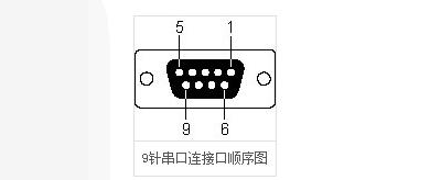
Cross-section of the line from the computer.
RS-232 pin function:
data:
TXD (pin 3): Serial Data Output (Transmit Data)
RXD (pin 2): Serial Data Input (Receive Data)
shake hands:
RTS (pin 7): Request to Send
CTS (pin 8): Clear to Send
DSR (pin 6): Data Send Ready
DCD (pin 1): Data Carrier Detect
DTR (pin 4): Data Terminal Ready
Ground line:
GND (pin 5): Ground
other
RI (pin 9): Ringer indication
2, RS-422RS-422 (EIA RS-422-A Standard) is the serial connection standard for Apple's Macintosh computers. RS-422 uses differential signals and RS-232 uses signals from unbalanced grounds. Differential transmission uses two wires to send and receive signals. Compared to RS-232, it provides better noise immunity and longer transmission distances. Better noise immunity and longer transmission distances in industrial environments are a big advantage.
3, rs-485/'target='_blank'>RS-485RS-485 (EIA-485 standard) is an improvement of RS-422 because it increases the number of devices, from 10 to 32, while defining the electrical characteristics at the maximum number of devices to ensure sufficient The signal voltage. With multiple device capabilities, you can use a single RS-485 port to establish a network of devices. With excellent noise immunity and multi-device capabilities, RS-485 is selected for serial connections when establishing distributed device networks connected to PCs, other data collection controllers, HMIs, or other operations in industrial applications. RS-485 is a superset of RS-422, so all RS-422 devices can be controlled by RS-485. The RS-485 can be serially connected over 4000 feet.
The basic structure of the serial portSBUF: 51 special registers in the microcontroller, serial data buffers (one receive and one send), two are actually shared at one address, 99H, but the two are physically separate.
When sending use, SBUF=XXX is used; (XXX is the data to be transmitted)
When receiving and using, use XXX=SBUF;
Remember that because it is serial, the transmission is performed by a single bit.
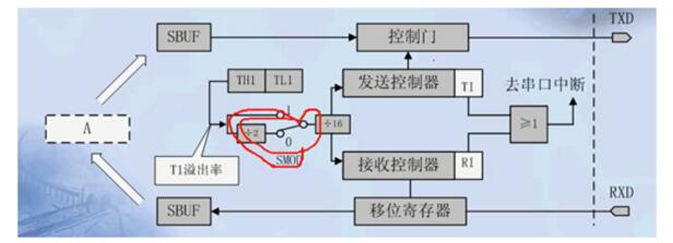
T1 overflow rate: The frequency of T1 timer overflow (it is the countdown time from the low to the high time of the timer)
Use: Used to calculate the baud rate (bits of transmitted binary code per second)
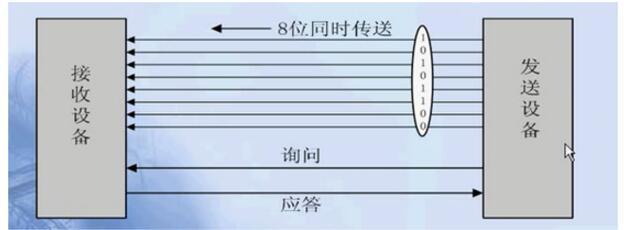
parallel
Suitable for short-range communication, parallel communication control is simple, relative transmission speed is fast (8-bit transmission).
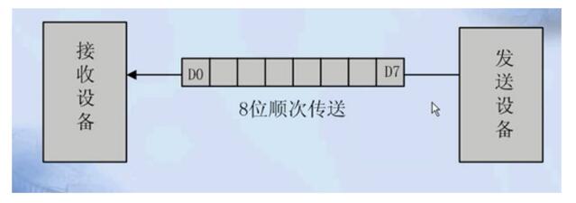
Serial
Can only be sent one by one.
Synchronize (know)
Establishes a direct control of the sender's clock to the receiver's clock, allowing both parties to achieve full synchronization. At this time, the distance between the bits of the transmission data is an integral multiple of the "bit interval", and no gaps are left between the transmitted characters at the same time.
The synchronization of the sender to the receiver can be through external synchronization and self-synchronization
Asynchronous (regular)
It is transmitted in units of characters (constituting frames). Data bits are transmitted from low to high.
format:
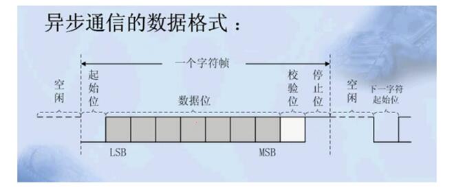
The free time here is arbitrary.
Serial Communication Protocol of Microcontroller C LanguageNow we have to do an experiment to send a byte from the 51 MCU to the computer serial debugging assistant. The purpose of this experiment is to grasp the process of sending and receiving serial communication protocols.
Virtual Serial PortExperiment 1, virtual serial port experiment
The general-purpose one-chip computer has specialized serial port pins, 51 inside are P3.0 and P3.1 respectively, these pins have the hardware circuit of the serial port, therefore use them to need not to set up sending of the signal and stop. In order to grasp the protocol, we use other pins to simulate the serial port, so it is also called a virtual serial port. Here we choose P1.0, but note that we 51 microcontroller to send data to the computer must go through a serial to USB device (ie, TTL level conversion to RS232 level), and only our development board only P3.0 and P3 .1 connected to a serial to USB device, so we can short P1.0 to P3.1. The following figure shows the schematic of this serial port to USB.
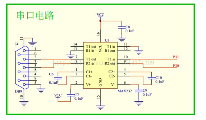
code show as below:
#include "reg51.h"
/*
P1.0 virtual serial port TX
Send data out at a bit rate of 9600 bit/s
Because the baud rate is 9600bit/s
So me sends one bit of time t=1000000us/9600=104us
*/
Sbit TX=P3^1; //P1^0 output TTL signal, need to transferred to rs232 signal, can be connected to P3^1
#define u16 unsigned int //Macro definition
#define u8 unsigned char
U8 sbuf;
Bit TI=0;
Void delay(u16 x)
{
While(x--);
}
Void TImer0_Init()
{
TMOD |= 0x01;
TH0=65440/256;
TH0=65440%256;
TR0=0;
}
Void Isr_Init()
{
EA=1;
ET0=1;
}
Void Send_Byte(u8 dat)
{
Sbuf=dat;// By introducing the global variable sbuf, you can save the parameter dat
TX=0; //A start bit
TR0=1;
While(TI==0); // waits for sending to complete
TI=0; //Clear Send Complete Flag
}
Void TF0_isr() interrupt 1 //enters an interrupt every 104us
{
Static u8 i; // records the number of interruptions
TH0=65440/256;
TL0=65440%256;
i++;
If(i)=1 && i“=8)
{
If((sbuf&(1′′(i-1)))==0) // (sbuf&(1′′(i-1))) indicates that the i-1 bit is taken out
{
TX=0;
}
Else
{
TX=1;
}
}
If(i==9) //stop bit
{
TX=1;
}
If(i==10)
{
TR0=0;
i=0;
Ti=1; //Send completed
}
}
Void main()
{
TX=1; //make TX idle
Timer0_Init();
Isr_Init();
While(1)
{
Send_Byte(65); //0x41
Delay(60000);
}
}
The experiment introduced Timer 0 to control the holding time of each bit on the transmission line. First, the main function enters, and TX is set to make the sending line idle. At this time, both the sender and the receiver are idle. Next, initialize timer 0. TR0 is set to 0 to not start timer 0 yet. Then interrupt the system initialization, this time the interrupt system has been opened. Enter the while loop, advanced Send_Byte () function, pass 65 to the parameter dat, dat assign 65 to the sbuf, ready to work here. Then TX is set to 0. This is the start bit. To maintain this start bit 104us. Then start the timer TR0 set and the timer starts counting. When the first time overflows, that is, after 104us, the interrupt is entered, and the receiver also detects the signal that it was suddenly pulled low, and then quickly starts its own timer. After entering the interrupt subfunction, first reload the timer initial value, then i plus 1, that is, when i = 1, it should send the lowest bit of the data, a total of 8 data, so use the conditional statement if (i) =1 && i "= 8) to judge whether to send data bit. Then send the stop bit through if(i==9). Finally, when i=10, it is finished sending. At this time, you need to close the timer (then the program) and i is set to 0 and ti is set to 1. Jump out of the while (ti==0) loop, and finally set ti to 0 to ensure that the program stays in while (ti==0) when the next byte is to be sent.
On-chip serial portThe above is a virtual serial port. The pins P3.0 and P3.1 related to the serial port are mentioned above. In fact, the 51-chip microcomputer comes with an on-chip serial port. How can this serial port be used?
On-chip serial ports support synchronous mode and asynchronous mode. In simple terms, the synchronous mode refers to the clock line, and the asynchronous mode has no clock line. The clock line here refers to a clock dedicated to the transmission of a clock signal during synchronous communication. This signal is used to keep synchronization with each bit to be transmitted. This avoids the introduction of timers in asynchronous communications, for example. error.
The on-chip serial port also supports 8-bit mode and 9-bit mode. As shown below
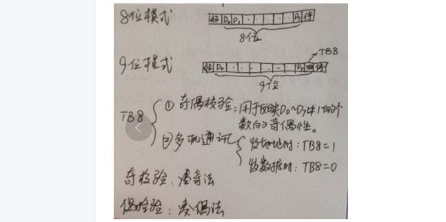
Where D0-D7 is 8 bits of a byte. 9-bit mode is only one more bit TB8, this TB8 role is parity or multi-machine communication. Parity principle without analysis. In multi-machine communication, for example, the host only sends data to a device at the address of 0x02 in the network. At this time, let TB8 be 1, and the preceding D0-D7 address is 0x02, and then let TB8 be 0. The preceding D0 -D7 is the data.
The on-chip serial port mode is set above, and the baud rate of the serial port is also set.
The baud rate of the on-chip serial port is equal to 32 divided by the overflow rate when Timer 1 operates in Mode 2. If Timer 1 is to operate in Mode 2, then TMOD = 0x20. In addition to ensure that the frequency is divided by 32, we must also set the initial value of the counter. Set the crystal oscillator to 11.0592Mhz, then the timer's count pulse is F=f/12, then the timer counts one pulse per time as T=12/f. Let the starting point of the counter be x, then the number of pulses to be counted for the overflow is (256-x). So when the counting starting point is x, the overflow time is t=12/f*(256-x). The corresponding overflow rate is 1/t=f/(12*(256-x)). The corresponding baud rate is b=f/(384*(256-x)).
x=256-f/(384*b)
Where f is the crystal frequency, b is the desired baud rate, and x is the value of the timer starting point TH1.
For example, when the crystal oscillator is 11.0592M and the desired baud rate is 9600 bit/s, then TH1=253. Digression, we can also calculate that in other common baud rates, TH1 is always an integer. Here is why 51 is selected inside the 11.0592M crystal instead of 12M, this ensures that the serial timing is more accurate, although at the expense of the accuracy of the timer.
In experiment 2, an off-chip serial port sends one byte.
Well now start our experimental journey. Look directly at the code.
#include "reg51.h"
#define u16 unsigned int
#define u8 unsigned char
Void delay(u16 x)
{
While(x--);
}
Void Uart_Init() // Serial port initialization
{
SCON=0x50; //8-bit asynchronous mode
TMOD|=0x20; // Timer 1 working mode 2
TH1=253;//9600bit/s
TR1=1;
}
Void Send_Byte(u8 dat)
{
SBUF = dat; // start sending, only need to send content to SBUF this register
While(TI==0); // Wait for sending to complete, because TI is 1 to send stop bit
TI=0;
}
Void main()
{
Uart_Init();
While(1)
{
Send_Byte('m');
Delay(60000);
}
}
Compared with experiment one, experiment two shows that the code is reduced a lot, and it does not need to consider the tedious bit sending sequence. Only need to understand the usage of each register SCON, TMOD, TCON, SBUF. TI is the first bit in SCON to send an interrupt request flag. In this mode, it is set by the internal hardware when the stop bit starts transmitting, and the TI must be cleared by software after the interrupt is responded to.
Experiment 3: Serial port on the chip sends a string
The above describes how to send a byte, how to send a string or even text? Here we first introduce the concept of string.
String: Starting from an address in memory, storing multiple characters of ASCII code consecutively, and storing a 0 after the last character, this continuous memory space is called a string, and the last 0 is the end of the string symbol. Note that the zeros and single quotes 0 are not a concept here, plus single quotes 0 refers to 0 ASCII code.
The relationship between arrays and strings: Strings are a special case of arrays, and arrays can be used as strings under certain conditions. The C language uses double quotes to describe a string, such as "abcd".
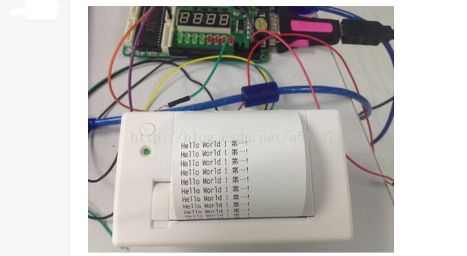
Below we show through an experiment how to send a string. The goal of our experiment is to print the string "Hello World! First!" to the printer. Directly on the code.
#include "reg51.h"
#define u16 unsigned int
#define u8 unsigned char
Void delay(u16 x)
{
While(x--);
}
Void Uart_Init() // Serial port initialization
{
SCON=0x50; //8-bit asynchronous mode
TMOD|=0x20; // Timer 1 working mode 2
TH1=253;//9600bit/s
TR1=1;
}
Void Send_Byte(u8 dat) //The serial port sends a byte
{
SBUF = dat; // start sending, only need to send content to SBUF this register
While(TI==0); // Wait for sending to complete, because TI is 1 to send stop bit
TI=0;
}
Void Send_String(u8 *str) // Send a string *str to the address of the first character of the string
{
Abc: //labeling
If(*str != 0)
{
Send_Byte(*str);
Str++;
Goto abc;
}
}
Void main()
{
Uart_Init();
While(1)
{
Send_String("Hello World! First!");
Send_Byte(10);
Delay(60000);
Delay(60000);
}
}
Experimental effect
Semiconductor Fuse And Ferrite
Fuse refers to an electric appliance that, when the current exceeds the specified value, melts the fuse and disconnects the circuit with the heat generated by itself.When the current exceeds the specified value for a period of time, the fuse melts and disconnects the circuit with the heat generated by the fuse itself.A current protector made from this principle.The fuse is widely used in high and low voltage power distribution system and control system as well as power equipment.
Ferrite is a metal oxide with ferrous magnetism.As far as electrical properties are concerned, the resistivity of ferrite is much larger than that of single metal or alloy magnetic materials, and it has higher dielectric properties.Ferrite magnetic energy also shows high permeability at high frequencies.As a result, ferrite has become a non-metallic magnetic material widely used in the field of high frequency and weak current.Due to the low ferrite magnetic energy stored in the unit volume, saturated magnetic induction strength (Bs) and low (usually only pure iron 1/3 ~ 1/5), and thus limits its higher requirements in the low-frequency magnetic energy density in the field of high voltage and high power applications.
Semiconductor Fuse and Ferrite,Fuse Cutout, Protection Fuse, Square Fuse, Fuse Link, Ceramic Fuse
YANGZHOU POSITIONING TECH CO., LTD. , https://www.cnchipmicro.com