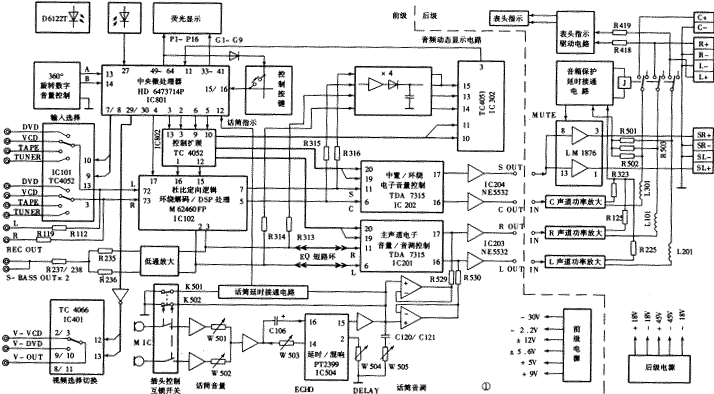
Qisheng AV-747DB is the latest home theater AV center launched by Qisheng, adopting front and rear split structure. Its predecessor uses the HD6473714P microprocessor as the control center, and the super large scale integrated circuit M62460FP as the core of Dolby Pro Logic Surround Sound Decoding (PRO.LOGIC) and Digital Surround Sound Field Effect (DSP) processing, and the TDA7315 controls the main channel ( L, R), center channel (C), surround channel (S) volume, tone adjustment. All functions of this machine except the karaoke system have realized full digital control and remote control. Thanks to the use of a fluorescent display for operation instructions, the man-machine dialogue function is greatly enhanced, making the operation very simple and clear. The rear stage performs independent power amplification on the L, R, C, and S channels, and the output power is strong. The output protection circuit has functions such as power-on noise suppression, over-current protection, over-voltage protection, and output short-circuit protection. The karaoke circuit of this machine adopts the PT2399 reverberation integrated circuit, which has a better performance on human voice. The microphone volume, tone and reverb depth, delay time and other control circuits are designed separately, and users can adjust it according to their own preferences. Almost every winding in the front / back stage power circuit is equipped with a fuse to ensure the safety of the whole machine. The machine is also equipped with a subwoofer line output and two-way video selection switching function, which is very convenient to use. The principle block diagram is shown in Figure 1. |

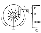
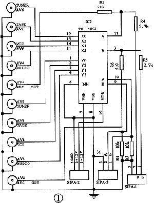
| The signal flow and working principle of the AV-747DB power amplifier are introduced below. The L and R audio signals from the signal source are selected by the dual 8-channel electronic selector switch of IC101 (TC4052), and come out from pin ③ and {13}, and go in two ways: one is isolated by R112 and R119. For recording output; the other way enters the sound field processing circuit from the {72} and {73} pins of IC102 (M62460FP). M62460FP is a very large-scale integrated block with 80 feet, which contains PRO · LOGIC decoding, DSP sound field processing, digital delay processing, Dolby noise reduction, sequence noise test (TEST) and electronic switch control and other functional circuits. It can complete the selection of processing methods such as BY-PASS (signal through), PRO · LOGIC, 3STEREO (Dolby three-channel stereo) and DSP. In the PRO · LOGIC state, the output states and signal components of S, C, R, and L can be controlled, and the center sound field can be converted into NORMAL (normal), WIDE (wide), PHANTOM (phantom) and other modes. Adjust the delay time of 15 ~ 30ms for the surround. In the DSP state, control the internal electronic switch, can choose HALL (hall), MUSIC (concert hall) and other eight sound field modes, and can adjust the delay of 15 ~ 50ms. After the L and R audio signals are processed by the M62460FP, the center (C) and surround (S) signals are generated and output from the ⑤ pin and the ⑦ pin (the C and S channels are not output in the through state). Sent into IC202 (TDA7135) for volume control, and sent to audio dynamic display circuit via R315 and R316 at the same time. In addition, the processed main channel R and L signals are output from pins ② and ③ of IC102, and then transmitted in three directions: (1) After low-pass amplification, the subwoofer signal below 150 Hz is left (S-BASS ) After R235 and R236 isolation and mixing, line output is provided for users to choose. (2) Send to dynamic audio display circuit via R313 and R314. (3) After the output and input interface of the equalizer (EQ), enter the volume and tone adjustment circuit from the ⑥ pin and {11} pin of IC201 (TDA7315). TDA7315 is a professional volume, tone, and balance electronic adjustment integrated block. It adopts bus control technology and can control the volume, equal loudness (LOUD), high and low tone (TREBLE, BASS), and left and right balance (BALANCE) of two signals. Make adjustments. It also includes an electronic mute switch MUTE, so it can easily realize the mute function of each channel. Only the volume adjustment and mute switch are used in the center and surround of the machine, and the others are fixed. The main channel uses all its functions. The R, L, S, and C signals are output from the {17} and {16} pins of the two integrated blocks IC201 and IC202 after being adjusted by the volume and tone adjustment circuits, and then amplified by the NE5532 and transmitted to the audio coaxial cable. Post level. The R and L signals are superimposed on the signal from the karaoke system before the output is amplified. The audio dynamic display circuit is composed of a signal smoothing circuit and a signal sampling circuit. The R, L, C, and S signals are amplified, rectified, and smoothed, respectively, to become a smooth signal representing the dynamic amplitude of the original signal. The R and L signals sent to the sampling circuit are from the {13} pin, {of IC302 (TC4051) 14} Enter by foot. Because the C and S channels are combined in a segment on the display for dynamic display, the C and S signals are mixed into one channel here, and enter the sampling circuit from the {15} pin of IC302. The IC302 is controlled by the CPU, and at a rate of 18ms / time, the signals provided by the {13}, {14}, and {15} pins are scanned and sampled one by one, taken out from the ③ pin, and sent to the {11} pin of the IC801, and then through the CPU After processing, the display is driven to display. After pre-amplification of the two microphone (MIC) signals, their signal amplitudes are controlled by W501 and W502 volume potentiometers, respectively. In order to compensate the signal loss of the volume control circuit, after the two channels are mixed, they are amplified again. Then enter the {16} pin of IC504 (PT2399) through C106 and low-pass network. After the low-pass amplification, it is divided into two channels: one channel is directly output from the {15} pin of IC504, and the other channel is A / D converted and digitally extended. Time, D / A conversion, low-pass amplification, etc. are output from the {14} pin, and then returned to the {16} pin via the potentiometers W503 and C106, so that the delay is repeated cyclically, thereby generating echo. W503 can control the attenuation of the reverberation signal to adjust the depth of reverberation (ECHO). In addition, adjust IC504 ② external W504 feet can control the delay time (DELAY), in order to call up your favorite effects. The processed microphone signal is amplified and divided into two channels: one channel is output by two channels after the tone adjustment network of the microphone, and isolated by the radio follower, and superimposed with the R and L signals of the main channel; the other channel enters the microphone Squelch circuit. In order to avoid the electrical noise of the karaoke system entering the main channel when the microphone is not inserted, affecting the sound quality of the main channel, and generating "bang" impact noise when the microphone plug is inserted, the machine has designed a microphone mute circuit, which is delayed by the microphone The connection circuit is composed of a plug control interlock switch and is controlled by the microphone plug: when the microphone plug is not inserted, K501 and K502 are normally closed, where K502 directly connects the signal path of the karaoke circuit to the ground provided by K501 Level, the electronic switch of the delayed connection circuit is turned on, and the karaoke channel is also grounded. At the same time, the {12} pin of IC801 (CPU) is low, and the microphone symbol in the display does not light. When the microphone plug is inserted, K501 and K502 are disconnected under the top contact of the plug, the {12} foot of IC801 is raised to a high level, and the microphone symbol in the display lights. At this time, the electronic switch in the delayed connection circuit is controlled by the time capacitor, and continues to be connected, and the microphone circuit has no output. The capacitor is discharged for a period of time. When the voltage across the capacitor is lower than the threshold level of the control terminal of the electronic switch, the switch is opened and the karaoke circuit is normally output. The AV-747DB preamp uses HD6473714P as the central microprocessor and adopts bus control technology, which makes the realization of various functions very easy, simple and reliable, and greatly simplifies each control circuit. Like the microprocessor circuit of the color TV, the manual control commands of the AV-747DB mainly come from the infrared remote control and the local control buttons: after the infrared remote control signal is received and shaped by the receiving head, it enters the microprocessor from the {27} pin of IC801 . The key control signal enters the microprocessor from the {15} and {16} pins. The machine uses a 360 ° bidirectional rotation control mechanical pulse generator for volume control. When rotating clockwise / counterclockwise, the {13} and {14} pins are continuously connected to and disconnected from the ground to obtain pulse signals. As shown in Figure 2, because the contact points of the two fixed arms of A and B and the rotating disk are not on the same radius axis, when twisting the rotating disk, no matter in which direction, there must be a first to connect / disconnect with the ground , So that the pulses obtained by the {13} and {14} pins have a prior sequence, the microprocessor determines the volume is increased or decreased according to the timing of the two pulses. In addition, the greater the angle of twisting the rotating disk, the more the on / off times of the two fixed arms of A and B are connected to the ground, and the more pulses are acquired by the {13} and {14} pins, the microprocessor It is based on the number of these two pulses to determine the level of volume up / down.  After processing various instructions and status information, the microprocessor IC801 drives the fluorescent display screen to display related information while outputting to various controlled circuits to realize various functions. Because the I / O interface of IC801 is not enough, IC802 is added as an interface extension to meet various requirements. |

Follow WeChat

Download Audiophile APP

Follow the audiophile class
related suggestion
〖Example 1〗 Fault Phenomenon A Qisheng AV-737 power amplifier is combined with VCD, connected well ...
